|
<< Click to Display Table of Contents >> Comparisons between measured and simulated values |
  
|
|
<< Click to Display Table of Contents >> Comparisons between measured and simulated values |
|
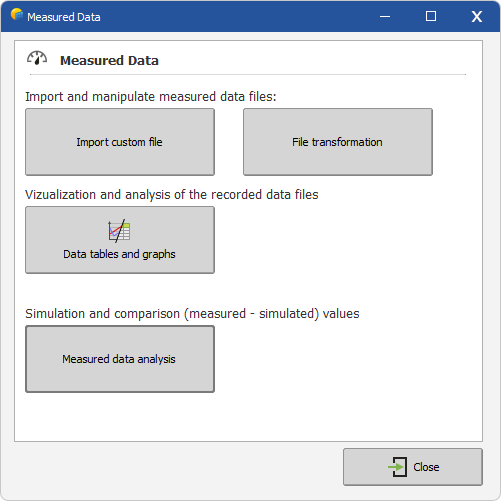
- Importing custom measured data files: allows to import measured hourly (or sub-hourly) data in almost any text CSV format.
- File transformation: technical tool for merging and cutting PVsyst measured data files.
| - | Data tables and graphs: powerful tool for visualizing and checking hourly measured data files. |
- Measured Data Analysis: parameter definition, simulation, and close comparisons between measured and simulated data.
The Comparisons between measured and simulated values is a very similar process as the Simulation process.
The main difference is that the original Meteo file of the project is replaced by the measured data file, which is attached to each variant (so that the Project can treat several measured data files, for example for different periods).
Therefore the measured data file should contain the meteorological data necessary to carry out the detailed hourly simulations.
Regarding other aspects, the Project and parameter definitions organisation is exactly the same.
Procedure:
After choosing "Project Design" and the system type in the main window, the procedure is the following:
- First define the Project through the "Project/Variant" button. You can also retrieve an existing project through the "File" menu.
- For each variant, define the plane orientation.
- Define the System properties.
- The program verifies the consistency of all parameters, and produces "Warnings" as Orange (acceptable for simulation) or Red (preventing simulation) LED's.
- When available (all parameters properly defined, that is only Green or Orange LED's), press the "Simulation" button.
- When the simulation is completed, you will enter the "Results" dialog.
In a second step, you can define if necessary :
- a Horizon profile (far shadings),
- Near shadings, that is partial shadings of near objects, which require a rather complex CAO 3D construction of the PV-field environment.