|
<< Click to Display Table of Contents >> Controller Operating Thresholds |
  
|
|
<< Click to Display Table of Contents >> Controller Operating Thresholds |
|
The controller' functions in operation are mainly for the protection of the battery:
| - Charging ON / OFF: | Disconnect the PV array when the battery is full, and reconnect it when necessary, |
| - Discharge OFF / ON : | Disconnect the load when the battery is empty, and reconnect it when possible, |
| - Backup ON / OFF : | If a back-up generator is available, start it when the battery is empty, and stop it when sufficiently charged. |
These operations should be performed according to the battery's state of charge (SOC). The decisions during operating may be based:
| - either on the battery voltage |
| - or on the battery State of charge |
Working with Battery voltage thresholds
This is the principle of most controllers, especially the little ones and of older generations, as it is simple to manage electronically.
However, due to
- the low voltage variation of the lead-acid batteries (low slope according to the SOC),
- the high temperature dependency,
- the voltage drop due to the battery internal resistance (and therefore depending on the current),
the relation between the battery voltage and the SOC is very difficult to establish.
Temperature effects
The Lead-acid batteries temperature coefficient is usually around -5 mV/°C (per element).
And the slope of the voltage dependency is about 180 mV for SOC passing from 0 to 1 (linear component of the model).
Therefore a variation of 5°C of the battery temperature corresponds to a shift of 0.14 on the SOC corresponding value for a same voltage !
This is the reason why it is absolutely required that the controller's voltage thresholds have a temperature correction, corresponding to the battery's temperature behavior.
Most controllers include this temperature correction, but many of them measure the controller's temperature instead of providing a temperature sensor to be fixed on the battery.
The reference voltage thresholds should by specified for a given reference temperature, which is usually 20°C for most controllers.
In PVsyst we define Reference Voltage Thresholds (at controller's ref. temperature) and Effective Voltage Thresholds (at the battery temperature) in operating conditions.
The corresponding SOC will be the same at each temperature, only if the Battery temperature coefficient is equal to the Controller temperature coefficient. This is not always possible: according to the manufacturer's specifications, the battery's coefficient is often between -4 and -5.5 mV/°C.
Current effects
Another problem arises from the charging or discharging current through the internal resistance.
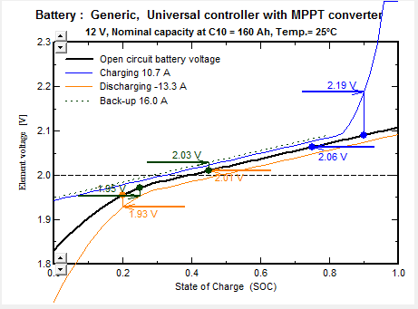
PV array Charging control: On the figure below, we can observe that the charging disconnect condition is rather easy, as the voltage slope is enhanced by the "gassing" phenomenon (dissociation of the electrolyte), which adds a significant voltage "loss".
However when the controller switches OFF, the battery voltage brutally drops to the "linear" behavior (or more exactly a curve corresponding to the discharging current if a load is connected). The reconnecting voltage should of course not exceed this voltage, otherwise the system will oscillate.The reconnecting voltage is very difficult to establish and optimize, because we move on the linear SOC region with low voltage variation, and the controller doesn't "know" the load current. When the system attains the reconnecting point, it will jump to the blue charging curve.
NB: The "Gassing" region is a dangerous mode for the battery, as it will consume some electrolyte. This is the reason why the disconnect recommended thresholds are usually lower for sealed batteries, because you cannot refill the electrolyte. Usual recommended values for max. charge disconnect are 2.28 V for open and 2.25 V for sealed lead-acid batteries at 20°C. However this is not the exact values we will put as default in PVsyst, as we are not sure that the battery model of PVsyst exaclty reproduces the actual voltage of all real batteries. Moreover, this value is also dependent on the charging current and the internal resistance.
For the reconnect threshold, the choice is more difficult. We did not identify reliable general recommendations in the literature.
PV array new charging strategies: modern controllers are now able to regulate the charging current using PWM techniques. When attaining the maximum charging voltage, they will limit the current for keeping a constant voltage (floating mode). In a solar system, this is very useful for compensating the load current if any: the PV array will provide the required load current, ensuring a null current in the battery.
Connecting several controllers in parallel (each one connected to one PV sub-array) may have a similar effect: as soon as one of these devices reaches its own threshold, it will switch off its array, and the global battery voltage will drop accordingly, delaying the switching of other controllers, and ensuring the PV production for satisfying the load if any. The PVsyst simulation acts in this way.
NB: In these situations, the Disconnecting threshold should be significantly reduced (below the Gassing region), otherwise we can have a "constant" gassing state which will consume a lot of electrolyte.
Load disconnect control: when approaching deep depth of discharge the PVsyst battery model also defines an enhanced voltage drop, which facilitates the decision of switching OFF. However this voltage is highly depending on the discharge current, especially for batteries with high internal resistances. Again, when disconnecting the load the voltage will suddenly increase, and we should be sure to specify a sufficient hysteresis for the reconnecting threshold, at least above the orange point, for avoiding oscillations.
The reconnection should ensure a significant SOC increase, but the reconnection voltage is extremely sensitive (18 mV for a SOC variation of 0.1), and the uncertainties due to the temperature and other phenomenons is important. .
Back-up generator management: when a genset is managed by the controller, the start of the genset should arise before cutting the load for deep discharge of course ! Therefore the BackUp ON threshold should be above the Discharge OFF voltage condition. Again, the reference point for starting the genset is situated on the orange curve.
But the stopping voltage condition will take place on the blue dotted line. As the current provided by the genset is usually rather high, the stopping threshold should take the voltage drop of the charging current into account. Avoiding oscillations and ensuring a reasonable recharge will require a big hysteresis !
Working with State Of Charge thresholds
As we have seen the determination of the SOC from the battery voltage and temperature is rather difficult and not reliable.
Modern controllers are equipped with microprocessors and memory, which may be used for an estimation of the SOC from a current balance measurement.
However there are also difficulties. The real battery capacity is never known with accuracy: it is depending:
- on the charge/discharge instantaneous currents,
- on the temperature,
- on the age and history of the battery.
- moreover the gassing current is not accounted in the SOC.
The only way of determining the capacity during operation is to use the current balance between rather well determined reference SOC, which are the beginning of the gassing and a given voltage during deep discharge.
Therefore for using the State of Charge estimation modelled from the current's balance, we have to reach periodically one of these reference points.
In a solar system, we can walk between these points during a long time, without reaching them, and therefore loose the SOC information accuracy.
Now controllers may use the voltage at extreme conditions (Charge cut at gassing overvoltage, or Discharge cut at deep DOD voltage), and the current balance information for the reconnection, as we have seen that this is a major problem with voltage thresholds.
PVsyst Implementation
The SOC determination is not a problem, as it is a basic variable of the simulation process.
In the older versions of PVsyst, the control was done with Voltage thresholds only, without efficient tool for the determination of these thresholds. The analysis of the behavior during the simulation was only possible "a posteriori" by using the SOC hourly curves.
Since the version 6.40, you have the choice of performing the simulation either with SOC thresholds, or with Voltage thresholds.
And the default values are usually specified in terms of SOC, which is much more stable than the voltages. It is more independent on the battery model (this will also allow the use of different battery technologies in the future).
You have now a visual tool for a deep analysis of the voltage thresholds and the relationships between the the voltage (at different temperatures) and the SOC thresholds.
Please observe that we have 3 different Threshold variables:
| - The VThreshRef | value is the reference switching voltage specified for the reference temperature of the battery. |
| - The VThreshEff | value is the effective switching voltage at the real (measured or simulated) battery temperature. |
| - The SOCThresh | value is the corresponding SOC of the associated battery, depending on the temperature and current. |
The tool (diagram above) shows that the relations between these 3 values are the following:
| - | The difference between VThreshEff and VThreshRef is only related to the Controller's temperature coefficient |
| - | The SOCThresh with respect to the VThreshEff is "a priori" only dependent on the Battery Current. However if the battery temperature coefficient is not the same as the controller's one, there will also be a temperature dependency. |
| - | The SOCThresh with respect to the VThreshRef is depending on both the temperature and the currents. |
You are advised to play with these parameters for a better understanding of the relationships and their consequences.