|
<< Click to Display Table of Contents >> Project design |
  
|
|
<< Click to Display Table of Contents >> Project design |
|
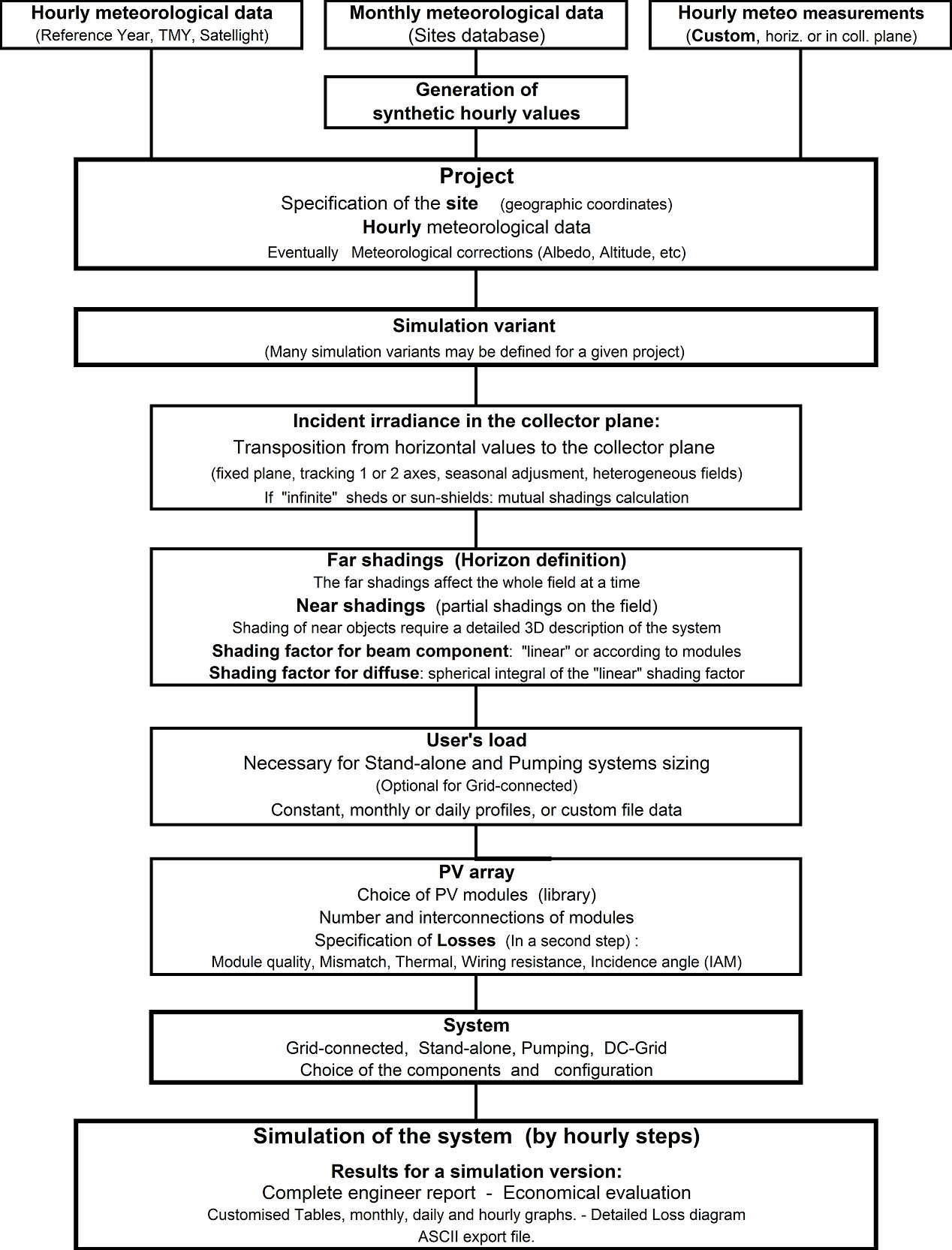
This part aims to perform a thorough PV-system design and performance analysis using detailed hourly simulations.
These are organised in the framework of a Project, which essentially holds the geographical situation and meteorological hourly data. Optimisations and parameter analysis can be performed through different simulation runs, called variants.
Procedure:
NB: You have a step-by-step tutorial to create your first project.
After choosing "Project Design" and the system type in the main window, the procedure is the following:
- First define the Project through the "Project/Variant" button. You can also retrieve an existing project through the "File" menu.
- For one Project (including basically Geographic Location and Meteo, with eventual Albedo data), you can construct different system variants (as many as you need).
- For each variant, define the plane orientation.
- Define the System properties.
- The program verifies the consistency of all parameters, and produces "Warnings" in Orange (acceptable for simulation) or Red (preventing simulation) LED's.
- When ready (all parameters properly defined, that is only Green or Orange LED's), press the "Simulation" button. Red buttons or warnings indicate bad definitions which prevent the simulation.
- When the simulation is completed, you will enter the "Results" dialog to consult the main results on the "Report" document.
- After simulation, each variant may be saved for further comparisons (please use "Save as" to avoid overwriting your previous variants). You are advised to define a significant description for each variant, in order to easily retrieve them in the list and to obtain a suited title in your final report.
For a given project, you are advised to first construct a rough variant keeping all parameters to their proposed default values.
In a second step, you can define the required refinements:
- In the "System" definition panel, you can modify the "Detailed losses" (soiling, IAM, module temperature parameters, wiring resistance, module quality, mismatch, unavailability, etc).
- eventually define a Horizon profile (far shadings),
- Near shadings, that is partial shadings of near objects, which require a rather complex CAO 3D construction of the PV-field environment.
- Module Layout for a description of the PV modules in the system, for the detailed calculation of the electrical shading losses.
The following diagram shows an outline of the project's organization and simulation process.