|
<< Click to Display Table of Contents >> Stand alone system definition |
  
|
|
<< Click to Display Table of Contents >> Stand alone system definition |
|
Stand-alone systems are always organized around a battery storage:
- a PV array charges the battery or directly delivers its power to the user.
- the user's needs (consumption) should be well defined, with its daily profile (i.e. in hourly values).
At each hour, the simulation performs a balance between the PV production (depending on the irradiance) and the user's needs. The difference should be derived in the battery, either positively (charge) or negatively (discharge).
This energy balance is controlled by a controller. The role of the controller is to handle the energy flux, mainly for the protection of the battery:
- When the battery is full, the PV array should be disconnected.
- When the battery is empty, the user should be disconnected.
Moreover, the controller may manage the starting of an eventual back-up generator (Genset), when the battery is empty and the solar gain is not sufficient.
In any case, the reconnexions will be performed with a specified hystersis, depending on the state of charge (SOC) of the battery.
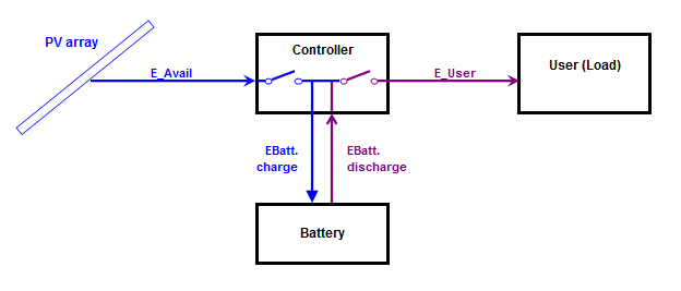
Very little stand-alone systems (SHS: Solar Home Systems):
This concerns little systems (50 to 200 Wp) with a very limited consumption (some lights, radio-TV, computer, no fridge).
With these simple systems, the PV array (one or few modules) is usually connected directly to the battery, without power conditioning. This implies that the PV modules should be "12V" or "24V" modules, i.e. with 36 or 72 cells.
This kind of installations is managed with very simple controllers, acting either by disconnecting the battery, or short-circuiting the PV modules when the battery is full.
These controllers have always the ability of controlling the load when the barr^ttery is empty.
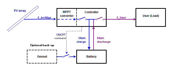
Medium power systems (Little household, communications)
These systems range usually between 200 Wp and 2 kWp.
The controller includes a power conditioning unit, able to perform the maximum Power Tracking on the PV array. Therefore the PV array voltage is no more related to the Battery pack voltage.
Most of the times, the controller is also able to ensure the load control, with a limited current capability (usually of the order of the charging current).
These installations may power lighting, fridges, wash machines, little electro-tools, etc. These may also be used in some little remote communication stations.
The energy may be used as DC energy, or fed as AC energy through a little inverter ("Battery inverter").
In the present time, PVsyst doesn't implement the inverter. The Load is specified as energy, whatever the way it will be used.
Such systems may - rarely - be supported by a back-up generator in case of lack of energy. If automatic, the Genset start/stop command should be managed by the controller.
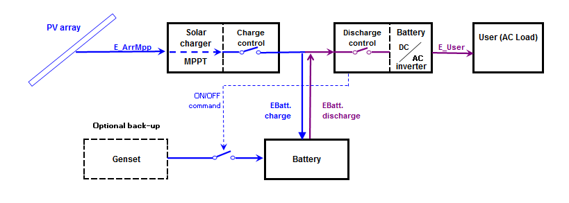
High power systems (Household, communication relays, isolated little industry, etc )
These may be stand-alone systems of 2 kWp to several dozens of kWp.
Such installations are using one (or several) "Solar chargers", equipped with MPPT converters, and DC/AC battery inverters.
The controller is no more a single device: the charging control is ensured by the Solar charger (sometimes several in parallel), and the discharge control by the inverter. The inverter should also manage the back-up generator if any.
In PVsyst, we consider the Solar Charger as the "Controller for Stand Alone" component. For historical reasons (and simplification) this PVsyst component has also to control the discharge and the back-up generator. But as the parameters for these functions are not defined within the "Solar charger" physical devices (data sheets), the internal parameters for these controls (maximum current, thresholds, etc) will remain in the dialog of this component, but their values will be defined within the system. Their initial values will be adapted from the system configuration, and will be modifiable according to the real Inverter used, or other other control device.