|
<< Click to Display Table of Contents >> Mismatch basic principles |
  
|
|
<< Click to Display Table of Contents >> Mismatch basic principles |
|
See also Array Mismatch Losses
The tool "String Mismatch" (available from "Detailed Losses") provides a set of tools, the 3 first ones dedicated to a detailed presentation of the mismatch principles.
The other options of this dialog are related to specific studies initially based on your system configuration.
The first option shows the I/V combinations explaining different mismatch situations:
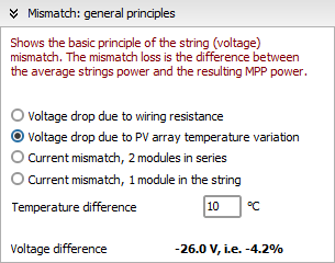
Voltage Mismatch
Let's begin with the voltage mismatch. We observe that the treatment of mismatch due to series resistance is different than for the array temperature.
In the first case the loss is proportional to the current, in the second case the voltage variation is about constant whatever the current.
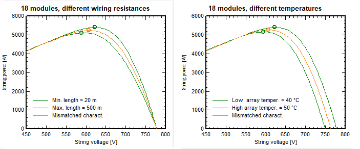
The behavior around Pmpp is rather equivalent. We can observe that the mismatch - i.e. the difference between the average Pmpp of the two strings and the Pmpp of the average string - is very low.
As an example, for exaggerated values:
| - | for a the string resistance of a 500 m wire (2.5 mm²) combined with a 0 m wire, the voltage drop is 5.2%, but the mismatch loss is only 0.38%. |
| - | for a temperature difference of 10°C, the voltage drop is 4.6% and the mismatch loss is 0.47%. |
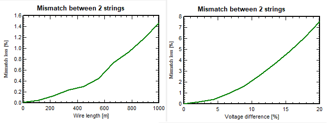
The next picture shows the evolution of the mismatch loss, as function of the wire length (2.5 mm²), or the voltage difference between 2 strings:
Current mismatch
The mismatch for the current is more complex, and there are many different situations.
Here PVsyst shows the case of a full string, with one only deficient module. The I/V and P/V curves show that:
| - | When the string current is below the Isc of the deficient module, the voltages are normally added. |
| - | When the current exceeds the Isc of the bad module, this becomes reverse-biased, the by-pass diodes become active. The bad module doesn't contribute anymore, moreover, the reverse voltage in the diode induces an additional loss. |
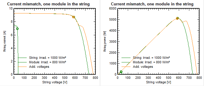
For this situation of one deficient module, the effective loss as function of the current deficit has a strange behavior:
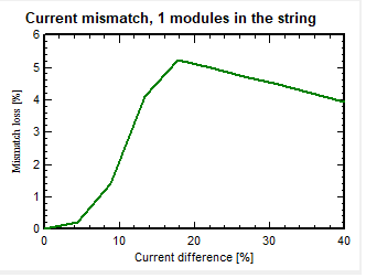
Up to the around 18% in this case, the Pmpp of the resulting curve (orange) is dominating.
Above this value, the maximum is indeed the Pmpp of the curve corresponding to the remaining modules (green on the graph above).
The (absolute) loss is the full "potential" contribution of the deficient module, plus the power lost in the diode when activated (decreasing in relative value).
Difference Current and Voltage mismatch
We can observe that the order of magnitude of the voltage mismatch (between strings) is much lower than for the current (within a string).
This may be explained by the fact that for the current, the worst cell/module current drives the current of the whole string. When for the voltage, the resultant is compared to the average of the Pmpp of each string.