|
<< Click to Display Table of Contents >> Array incidence loss (IAM) |
  
|
|
<< Click to Display Table of Contents >> Array incidence loss (IAM) |
|
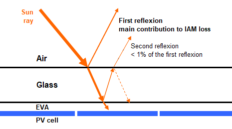
The incidence effect (the designated term is IAM, for "Incidence Angle Modifier") corresponds to the decrease of the irradiance really reaching the PV cells's surface, with respect to irradiance under normal incidence. This decrease is mainly due to reflexions on the glass cover, which increases with the incidence angle.
The transmission loss is a general phenomenon, due to the reflection and transmission of the sun's ray at each material interface (air-glass, glass-EVA, EVA-cell), as well as some absorption in the glass. This arises for any incidence ray. For normal incidence, the reflexion is of the order of 5%, and is included in the measured STC performance. The IAM only concerns the angular dependency of this effect, i.e. it is normalized to the transmission at perpendicular incidence (0° incidence angle).
PVsyst uses an IAM function, which describes the deficit of transmission as a function of the incidence angle. This function is applied either to the beam component, and to the diffuse and albedo, using an integral over all "seen" directions, supposing an isotropic distribution of the diffuse irradiance.
In principle, this phenomenon obeys the Fresnel's Laws describing transmission and reflections at the interface of two transparent materials of different refraction indexes n1 and n2.
This is a very general behavior, derived from the general Maxwell's equations describing all electric phenomena. The Fresnel's laws are first applied to the air-glass interface, they describe the reflected ray and the transmitted ray. For the transmitted ray, it is applied to the interface Glass-EVA, and so on.
These laws allow to calculate the light effectively reaching the cell's surface below the protective layer (usually glass), as a function of the incidence angle.
Now you can add an anti-reflective coating on the top interface air-glass. This thin layer has a lower refraction index than the glass, which limits the first reflection.
In the past, the IAM function has often been estimated using the "ASHRAE" parametrization (proposed in the years 80's by this American norm organism), depending on one only parameter bo:
FIAM = 1 - bo · (1/cos i - 1) where i = incidence angle on the plane.
For single-glazed thermal solar modules, the usually accepted value for bo is of the order of 0.1. But in a PV module, the lower interface, in contact with the cell, presents a high refraction index and our specific measurements on real crystalline modules actually indicate a value of bo = 0.05.
The Sandia IAM model has been used in the past for modules belonging to the Sandia database (not supported anymore). It is based on a 5th order polynomial interpolation (hence relying 6 coefficients from b0 to b5).
The model should not be used for models outside the database, although the option is available in PVsyst. In case one selects the Sandia model nonetheless, the following default parameters are used:
b0 = 1 , b1 = -0.002438 , b2 = 0.003103 , b3= -0.0001246 , b4 = 0.0000001211 , b5 = -0.00000000136 .
Up to the version 6.66, the Ashrae parametrization was used as default in PVsyst, whatever the module characteristics.
However since the version 6.67, PVsyst gives the opportunity of specifying the kind of glass interface (Normal glass, Anti-reflective coating, structured glass or plastic).
And attributes a default model according to this specification:
| - | All old modules (already defined in the database by version 6.66) remain with the Ashrae parametrization. |
| - | The new modules with "Normal glass" or "Plastic" will use the normal Fresnel calculation. |
| - | The new modules with "AR coating" or "Textured glass" will use the Fresnel calculation with AR coating. |
The next figure shows the IAM function for these 3 models:
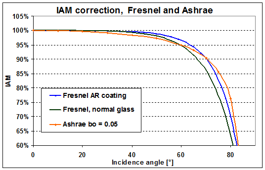
We observe that the Ashrae parametrization underestimates the IAM value at medium angles (30 to 60°) and overestimates them over these values.
The effects on the full year simulation may be studied in detail using the "Detailed study" button in the "Detailed losses" dialog.
They depend on the meteo data, the plane orientation, etc. As an example, a simulation in Geneva gave
| - | Fresnel Normal glass slightly lower than the ASHRAE (- 0.25%) |
| - | Difference Fresnel AR coating and normal glass 0.75%. |
Note that for bifacial systems the IAM losses on the rear side of the PV modules are always calculated using the simple Fresnel model for glass without anti-reflective coating.
The IAM model is defined with the PV module parameters, page "Additional data > Customized IAM".
Here you should define the glass surface type, and PVsyst will attribute the corresponding IAM model.
If you want, you can also specify a customized IAM profile, according to your experimental data.
However for the the database, if a manufacturer wants to set his own IAM profile, we require a detailed measurement report established by an independent laboratory. And we also require that this measurement is performed indoor.
The IAM model used in the simulation is defined in the "Detailed Losses" part.
By default, PVsyst will take the values specified for the PV module (of each sub-array). But you can also specify another profile for this present simulation. For example retrieve the default value for a module which has been specified with a customized profile by the manufacturer.
NB: The "Detailed Losses" dialog has a button "Detailed Study", which provides a complete analysis and helps understanding the IAM effects as function of the Irradiance angular distributions (beam, diffuse and albedo).