|
<< Click to Display Table of Contents >> Thin objects: effect on the electrical losses (Module strings calculation) |
  
|
|
<< Click to Display Table of Contents >> Thin objects: effect on the electrical losses (Module strings calculation) |
  
|
NB: This procedure is only useable with the "Electrical shading loss according to modules strings" procedure. There is no equivalent in the "Module Layout" for the moment.
Overview
If a shading object is sufficiently thin, its shade will not cover a full cell. Even if it is rather far and produces a broad semi-shading (due to the sun's diameter), the irradiance loss should be considered as the integral of the shading figure, and will be the same as the effect of a well delimited thin shading of the same wire.
This is the case of electrical wires above the array, handrails, etc. The case of electrical wires is particularly important, as it affects the array during the whole day.
In these cases the current in the cell will be reduced by a factor of the order of the wire diameter, with respect to the cell's size. We will call this ratio the "Thin Object ratio". Remember that in a string of modules, the current is limited by the worst cell (i.e. the cell with lower current).
We can take this situation into account in the shading calculation mode "According to module strings". In this mode the production of the whole string is considered lost as soon as one cell of the string is fully shaded.
In the case of thin objects, the cell current is not null, but reduced according to the "Thin Object ratio". Therefore the loss for the shaded string will be affected by the parameter "Fraction for electrical effect". As a first approximation, we can use the value of "Thin Object ratio" for this parameter.
See the paragraph "Effect of distance" below for e refinement of this value.
Thin object ratio
When a thin object throws a shade on a PV module (cell), the current in the cell will be limited to the illuminated area.
Let's call "Thin object ratio" the ratio of the thin object shade area, to the total area of the cell. The shading current reduction will be proportional to this Thin object ratio.
Now the thin object's position may depend on the cable orientation, or will move according to the sun's motion. We will assume that - on an average over any evolving conditions - it will be the wire width divided by the cell's size.

As an example, a wire of 300 mm2 has a diameter of the order of 20 mm. On a standard 6" cell, the thin object ratio will be 20 mm / 156 mm = 0.13.
Therefore, the current loss will be 13% in this cell. For the full string, the current will be the current in the worst cell, i.e. a loss of 13% whatever the number of cells shaded.
Effect of the distance
The sun diameter is 1.39 Mkm, at a distance of 149.6 Mkm of the earth. So that its apparent diameter (cone aperture) is 0,53°.
Now if you have a thin object of section S, at a distance D of the PV array, due to this diameter the shaded area will extend to a total width W = D * sin(0.53°) + S.
The Thin object tool is aiming to understand and evaluate this effect.
You will find this tool in the 3D editor menu, "Tools > Thin Objects Analyze tool".

You have to specify the object's width, the cell size and the distance of the object to the array.
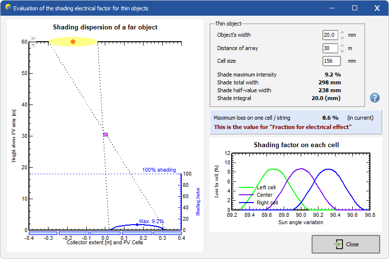
This tool will show the shade trail on the PV module.
If the cable is very close, we will have a sharp trail of 20 mm in width, with a full shading on this cell (20 mm / 156 mm = 13%).
The example here shows a cable at 30 m over the PV array: the shade trail is about 30 cm wide, i.e. split onto several cells. Therefore the loss on one single cell will be lower.
Sun motion and shades distribution
You can move the sun's position with the red point: the shade will move on the cells. The global shading effect on each cell is shown on the plot as function of the sun's position: the maximum shading factor on one given cell at a given time is 8.6%: this will be the value we have to attribute to the "Fraction for electrical effect" for this thin object.
NB: even if you have several wires over this PV modules string, the current of the string will be limited by this value. The shading effects are not additive !
Additional remarks
Whatever the distance of the thin object, the total shade on the array (i.e. lack of irradiance) is always the same. We can check with this calculation that the shade integral is always the same (20 mm / 156 mm) whatever the sun position or the object's distance.
On the other hand, in our case the shade maximum intensity is 9.2% , but this doesn't mean that the shade on one cell reaches this value: what is relevant is the integral on the full cell at a given time, which is shown on the plot.