|
<< Click to Display Table of Contents >> SubModules layout |
  
|
|
<< Click to Display Table of Contents >> SubModules layout |
|
Since some years, the architecture of the PV modules has strongly evolved. We find more and more modules with diverse internal organizations of submodules.
These are usually not explicitly described in the datasheets. We have sometimes difficulties for understanding the organization of the by-pass diodes in some exotic layouts (like "shingles).
Definition in the PV module dialog
The architecture is a basic definition of the PV modules parameters (PAN files), useful especially when dealing with electrical shadings.
It is closely related to the number of cells in series. The usual voltage of modern crystalline cells is 0.56-0.57 V/cell. Therefore the number of cells in series may be estimated using the specified Vmpp at STC.
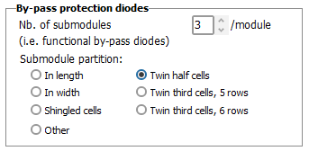
There are several other possible configurations. You can get them in an additional combobox, when checking "Others" in this dialog.
Submodules configurations description
We give here a description of each of these these definitions, with some additional information and constraints.
NB: the Module Layout tool for the study of electrical losses uses the submodules distribution and geometry, as it has to evaluate the shading state of each submodule. In the present state, only the traditional modules (in width or in Length) and the Twin half-cut cells modules have been implemented. We can also apply the Module Layout calculation to the twin third-cut cells with 5 rows, with a very good approximation.
All other structures are not suited for the Module Layout calculation.
|
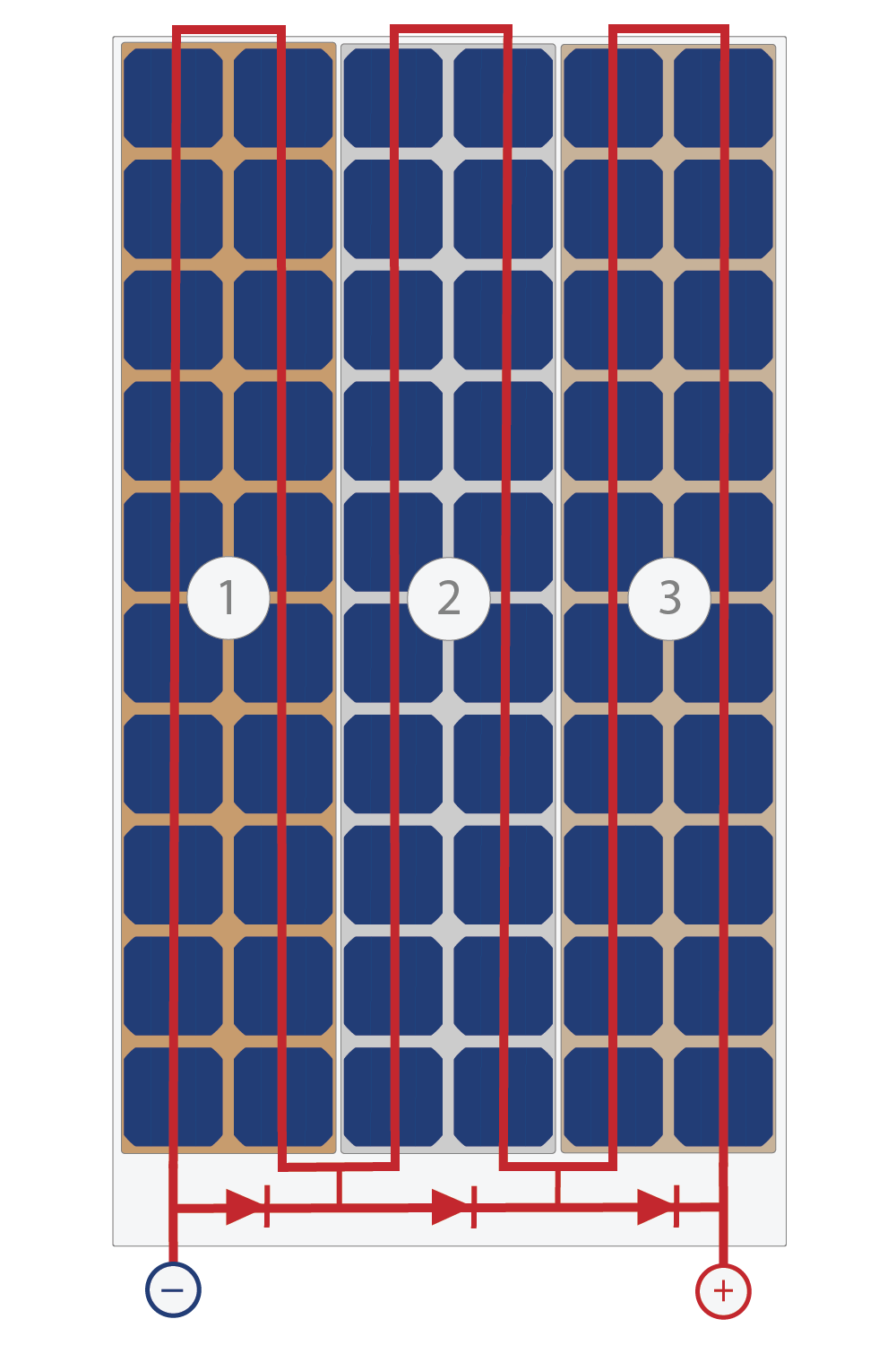
In Lenght This is the basic organization of all historical PV modules. The old modules of 36 cells had 2 submodules "In length", and therefore 2 by-pass diodes. The usual modules have now 60 or 72 cells (rarely 48, 54 or 96), with 3 by-pass diodes, i.e. 3 submodules "In Length". With cells of 156 to 166 mm, the gives module widths of the order of 0.99 to 1.05 m in width. The length depends on the number of cells. Modules of 60 cells are about 1.62 to 1.72 m, when modules of 72 cells have 1.93 to 2.04 m length. In these modules, the connexion of the by-pass diodes in a junction box requires a bus in the width of the module.
In Width Normally the modules of 96 cells should have 4 by-pass diodes. These could have 4 sub-modules of 24 cells each, i.e. groups of 6 x 4 cell organized in width within the modules. We don't know whether the modules of 96 cells are really constructed like that.
|
|
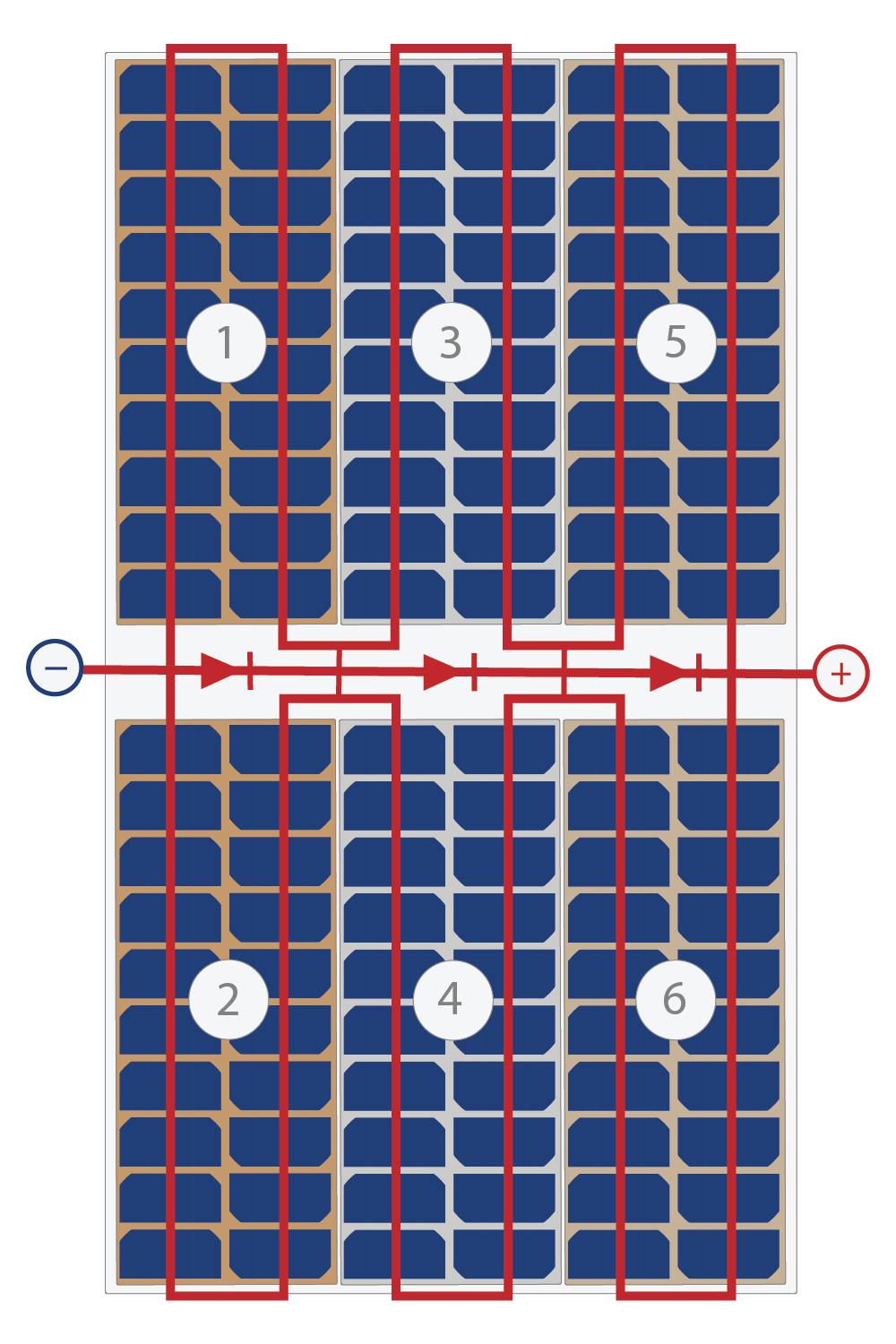
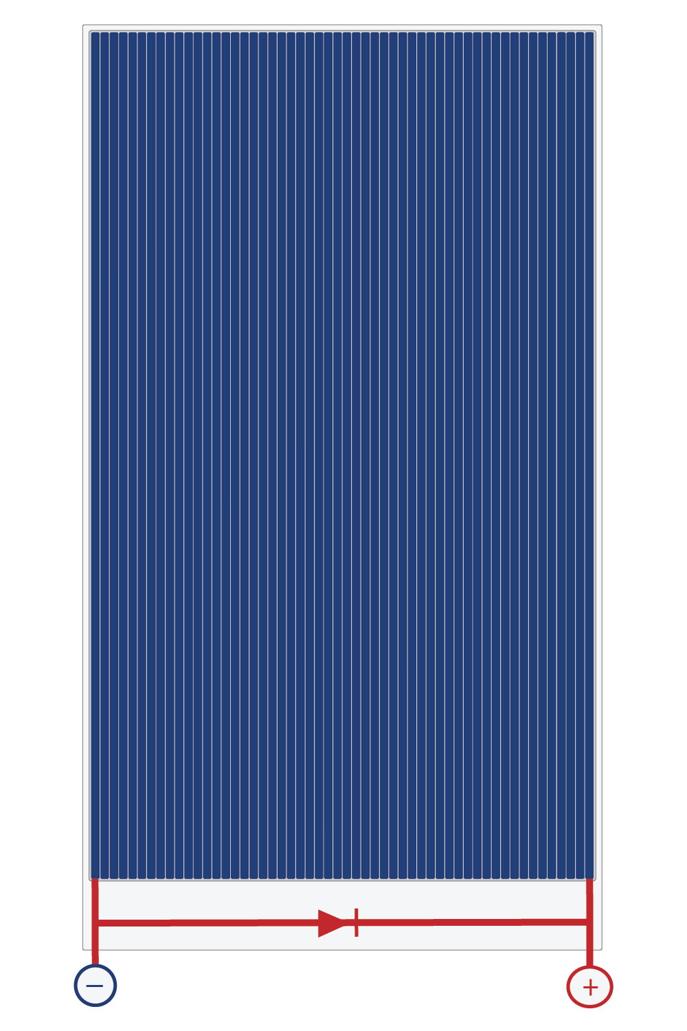
Twin half-cut cells . More and more modern modules are now organized in this configuration. This uses series of half-cutted cells. Each submodule is made of a series of 20 or 24 cells, and 2 submodules are connected in parallel, with one common by-pass diode. The advantage is that when some cells are shaded in the bottom part, the upper part of the module is still active, minimizing the electrical shading loss. Therefore in a row arrangement, these modules should be used in portrait. Each sub-module has 20 (or 24) cells in series. Therefore NCells in series = 60 (or 72), i.e half the total number of cells specified on the datasheets. And the number of cells in parallel is 2. The global sizes of these modules are comparable to the equivalent modules "in length". There are other technological advantages: this minimize the series resistance, and diminishes the risk of cracks. This technology seems to favor the efficiency: modules of a same manufacturing processes get slightly better efficiencies.
|
|
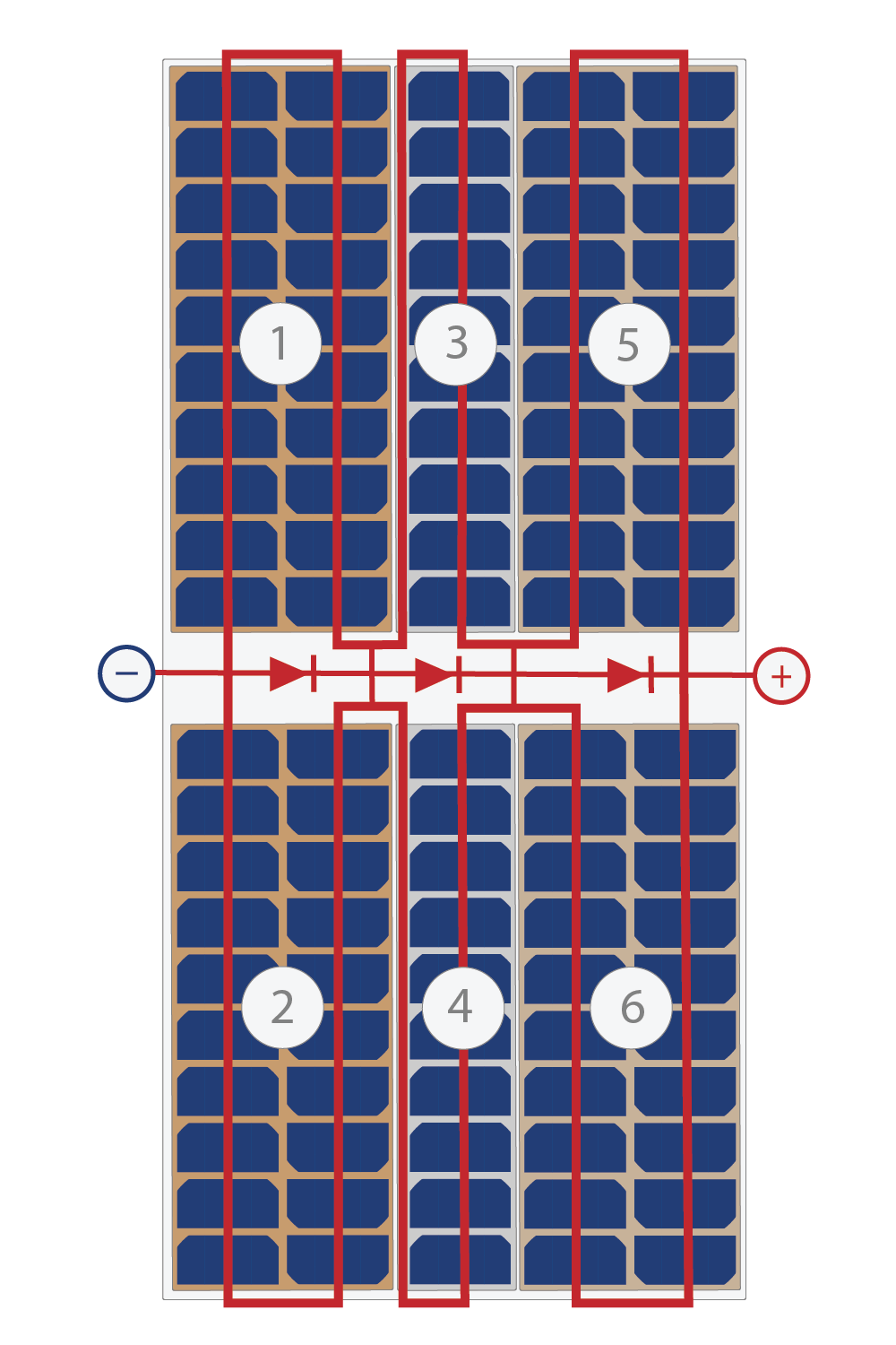
Twin third-cut cells, 5 rows . With the increase of the cell sizes (182 and now 210 mm), some manufacturers try to keep the PV modules close to usual sizes. They diminish the number of rows (5 * 210 mm lead for about 1.1 m width) and use 1/3 of cells for limiting the lenght - and also the current. The number of cells in series may be 22 + 11 + 22 (i.e. 55 cells) or 24 + 12 + 24 (60 cells), etc. It should be divisible by 5. This configuration requires that for the central submodule, a copper connexion strip leading the half-current of the module has to be deployed along the sub-module.
Twin third-cut cells, 6 rows There are also modules with big cells and 6 rows (6 * 210 mm leads to a module width of 1.32 m), with cells cut as thirds.
NB: We can also find in the database some modules with cut cells which are neither halves nor thirds cells (182 x 70 mm). |
|
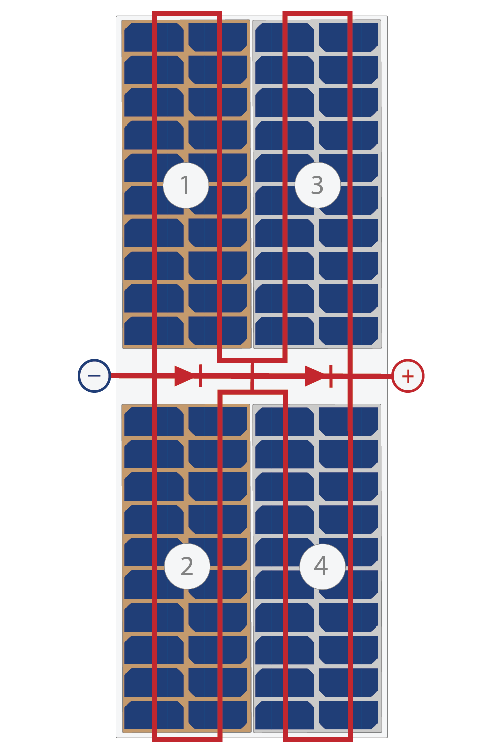
Twin half-cut cells, 4 rows There are also some few narrow modules with 4 rows of cells, and therefore 2 by-pass diodes. These seem to be especially designed for grid integration. |
Shingled cells Some modules are made of shingled cells, i.e. narrow cells (1/4, 1/5, or less) which are interconnected by superposition in the same way as tiles. There is a variety of possible layouts: sometimes all the cells in series are on one row in the module length, and these rows are connected in parallel. In other cases the rows are distributed in the width of the module, with a round trip layout. In any case, there is no information about the by-pass diodes protections.
|
|
Exotic Some modules have still other strange configurations, which we name "exotic" in this classification. For these special modules, where the submodules are not well defined (Shingle or exotic), the module layout model cannot be applied. |
|
|
Strips in length Strips in width In the thin film modules (CIGS, CdTe, amorphous) the cells are strips of about 10 mm width, on the full length of the module. In some cases, the strips may also be in the width of the module. This means that the number of cells in series is closely related to the modules size (width or length). Some Thin film modules have a very high number of cells (for example first Solar CdTe: 270 cells in series for a Vmpp around 185V). Most of the thin film modules have one only by-pass protection diode for the whole module. This is because the connection from cell to cell is indeed distributed on the whole length of the cells, so that it is not possible to get a middle point connection. This is not a problem because a single cell is unlikely to be shaded. When installed in a row-like system, the strips should always be disposed perpendicularly to the possible shades. In this way all cells will be partially shaded in the same way. Therefore the thin film modules are not suffering of electrical shading losses.
|