|
<< Click to Display Table of Contents >> Standard one-diode-model |
  
|
|
<< Click to Display Table of Contents >> Standard one-diode-model |
  
|
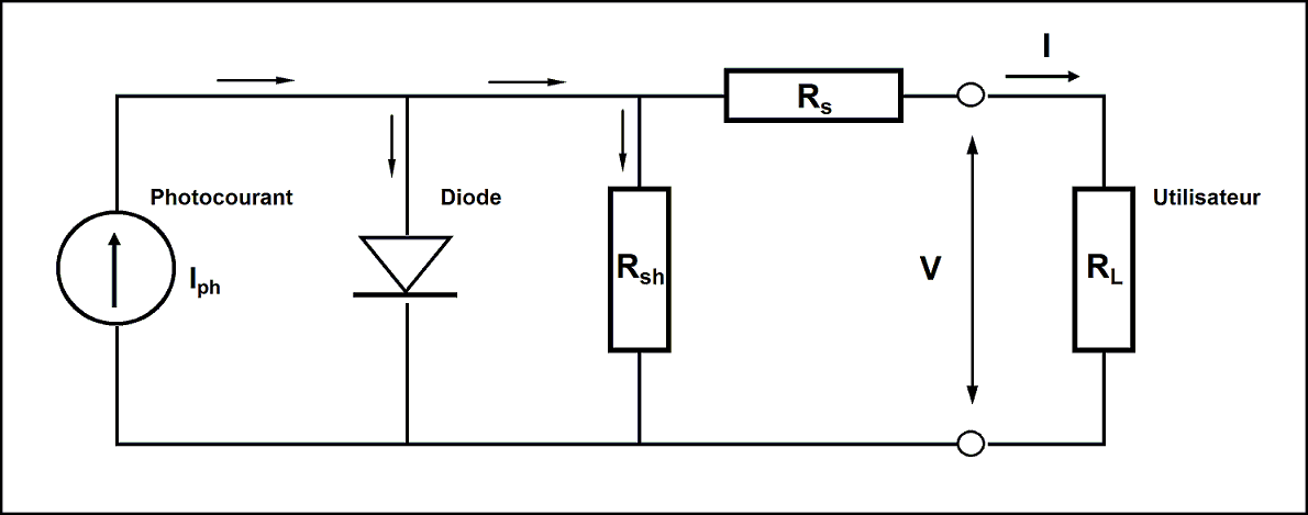
To describe the operating of a PV module, we use the Shockley's simple "one diode" model, described, for example, in Beckman and al. This model is based on the following equivalent circuit for decribing a PV cvell:

The model was primarily developed for a single cell. Its generalization to the whole module implies that all cells are considered as rigorously identical.
A more sophisticated model, implying 2 different diodes, is sometimes proposed for the very accurate modelling of a single cell. But in PVsyst, we think that small discrepancies in the cell parameters, inducing internal mismatch, as well as the moderate accuracy of our basic input parameters (usually from manufacturer), make no sense to use it. In the one-diode model the two diodes are considered identical, and the Gamma factor - ranging theoretically from 1 to 2 - defines the mix between them.
This model is well-suited for the description of any technology of Si-crystalline modules, but needs some adaptations for reproducing the thin film technologie module behaviour. We observed that the CIS technology obeys quite well to this standard model.
The main expression describing the general "one-diode" model for a given set of reference conditions (usually STC: 1000 W/m2, 25°C, AM=1.5) is written as:
I = Iphref - IoRef [ exp (q · (V + I · Rs) / ( Ncs·Gamma·k·Tc) ) - 1 ] - (V + I · Rs) / Rsh
with :
| I | = Current supplied by the module [A]. |
| V | = Voltage at the terminals of the module [V]. |
| IphRef | = Photocurrent [A] |
| IoRef | = diode inverse saturation current [A] |
| Rs | = Series resistance [ohm]. |
| Rsh | = Shunt resistance [ohm]. |
| Gamma | = Diode quality factor, theoretically between 1 and 2, often less |
| q | = Charge of the electron = 1.602·E-19 Coulomb |
| k | = Bolzmann's constant = 1.381 E-23 J/K. |
| Ncs | = Number of cells in series. |
| Tc | = Effective temperature of the cells [Kelvin] |
In this equation, we have 2 unknowns (in blue), five parameters to be determined (in green) and some physical constants.
The determination of the 5 parameters is described in the next topic. It involves the STC data usually specified by the manufacturer.
After obtaining the 5 parameter's values, we can solve the equation for getting the I/V curve, i.e any point I = f(V) or V = f(I). As the equation is implicit, this requires to use a successive approximations approach.
As function of the irradiance
The one-diode model assumes that the photocurrent Iph is perfectly proportional to the irradiance.
There is also a little dependency on temperature: a positive linear increase according to the muISC parameter, of the order of +0.05 % / °C.
Therefore for any conditions, the Iph will be determined with respect to the values given for reference conditions (Gref, Tref):
Iph = ( G / Gref ) · [ Iph ref + muISC (Tc - Tc ref) ]
| where G and Gref | = effective and reference irradiance [W/m²]. |
| Tc and Tc ref | = effective and reference cell's temperature [°K]. |
| muISC | = temperature coefficient of the short-circuit current [A / °C] |
As function of the temperature
The diode's reverse saturation current is supposed to vary with the temperature according to the expression:
Io = Io ref ( Tc / Tc ref )3 · exp [ ( q · EGap / Gamma · k) · ( 1 / Tc ref - 1 / Tc ) ]
| where | EGap = Gap's energy of the material (1.12 eV for cristalline Si, 1.03 eV for CIS, 1.7 eV for amorphous silicon, 1.5 eV for CdTe). |
This equation is derived from the fundamental solid state physics: it was proposed by the "inventors" of the first PV cells in 1950, and applies quite well to the reality.
It varies very quickly, as a function of the cube and the exponential of the temperature variations.
As function of the the spectral contents
The spectral correction is not included in the basic One-diode model.
In PVsyst, it as applied differently according to technologies:
- For amorphous modules, we have a parametrized correction as function of Kt and Air mass
- For crystalline and CIS, the dependency is extremely weak. It is neglected.
- For CdTe modules, a correction has been proposed by the main manufacturer of this technology. It is implemented, but without any guarantee from the PVsyst point of view.