Sketchup and other CAD software
It is possible to import shading scenes from other CAD softwares.
Supported file formats for Near shading import
- 3DS : An export option in many tools
- DAE : The Collada file format can be exported from many CAD software as it is an open format. It is available as an export format in Sketchup free version.
- PVC : PV Collada file, open-source format derived from DAE format to include data about the PV modules and tables
How to import 3D scene in the Near shading window in PVsyst
In order to import such a file, use the menu File / Import / Import a 3D scene (3DS, DAE, PVC).
Once imported, the new objects will be integrated in the current scene. After a successful import a dialog summarizing what was found in the imported file will appear.
Scene details
This panel summarise the number of imported objects and their total numbers of vertices and faces.
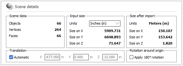
It also allows you to set the input unit in order to scale objects correctly in the PVsyst scene (currently always in meters).
When importing DAE files PVsyst will try to extract the unit from the file and set it automatically.
The import will be automatically translated to the origin (0,0,0) of the scene if the distance (measured from its closest point to the origin) exceeds 5 kilometers.You can however modify the translation parameters by unchecking 'Automatic' and by editing X, Y and Z.
There is an option to rotate all the imported objects by 180° around the origin (0,0,0) of the scene. This option is checked by default in the southern hemisphere and it is unchecked by default in the northern hemisphere. But you can check or uncheck it as you need.
PV objects
The second part of this dialog allows you define the orientation options for the import as well as selecting which materials in your file represent PV faces. The option for converting material to PV faces will not appear if you imported a PVC file, as PV information is already defined in the format.
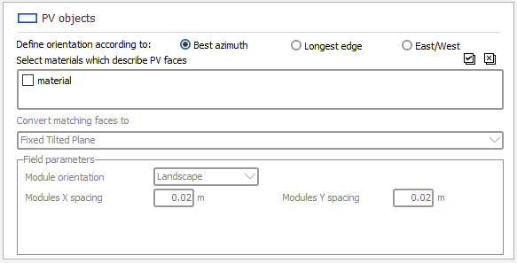
After selecting one or more materials the combobox will allow you to define which kind of PV field must be created in PVsyst after the import : fixed tables or trackers. If you select a tracker type then you will be able to specify the tracking parameters to apply depending on the type.
Orientation definition
The orientation can be defined using one of following three options:
- Best azimuth : PVsyst will try to optimize the azimuth of the table when defining its orientation. In this scenario PVsyst will define the orientation that has the azimuth closest to 0° (default behaviour in PVsyst V7.4.2).
- Longest edge : PVsyst will use the longest edge of each PV table to define its orientation (default behaviour before PVsyst V7.4.2).
- East/West : PVsyst will try to select an east/west orientation for the table. In this scenario PVsyst will define the orientation that has the azimuth closest to -90° or 90° (usually the best option for domes).
The bottom part of this dialog allows you to change the default behavior regarding orientations creation.
- If you keep the box 'Create multiple orientations' unchecked, a single averaged orientation will be created and used for all imported PV fields. The average is computed as the mean of the 3D unit normal vectors of all fields.

-
If you check the box, multiple orientations may be created. Fields are grouped based on the angular difference between their nominal orientation — that is, the orientation of each field as it would sit on flat ground, independently of the local terrain slope.
- For fixed tables, the nominal orientation is derived from the plane normal of each field.
- For single-axis N-S trackers, it is derived from the tracker axis direction — in practice, most trackers are differentiated by their axis azimuth.
Two fields are assigned to the same orientation if the angle between their nominal orientations is smaller than the threshold defined by "Angular difference between orientations". One orientation is created per group of similar fields, and orientations that are close enough to a pre-existing one are merged with it rather than creating a duplicate.

Importing ground topography
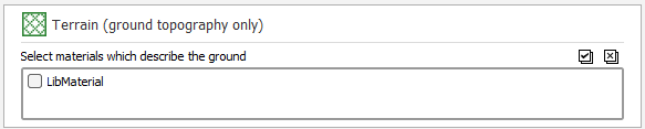
The file may contain ground topography. You can import this topography by selecting the materials which describe the ground.
Import from Autodesk AutoCAD
Importing from AutoCAD requires an additional step because it can't export directly to DAE.
You can either export your scene to Sketchup first and then to DAE (recommended option), or you can use a tool provided by Autodesk and called FBX Converter (which can lead to some issues, see below).
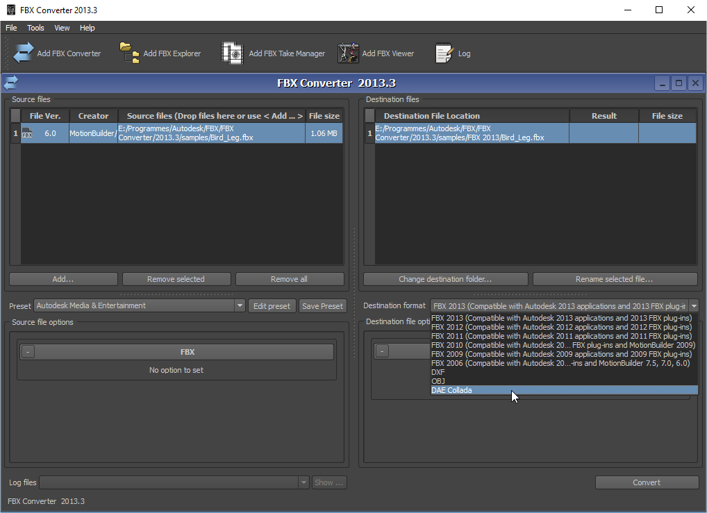
FBX Converter allows you to convert an FBX file generated from AutoCAD (and some other Autodesk products) to some other formats including DAE. WARNING: Using FBX Converter can result in some objects being slightly misplaced in the resulting DAE file. If you use this method, we recommend to carefully check the placement of objects and PV panels in the shadings scene of PVsyst after import.
This way it is possible to import your scene in PVsyst.
Limitations
Because PVsyst is used to simulate the shadings on PV fields its performance is directly related to the complexity of the shading scene.
Importing very detailed scenes from Sketchup or any other software is possible but not recommended as it will make the calculation time grow exponentially.
PVsyst will not be able to simplify objects geometry but you can still :
- Delete useless objects from the scene
- Disable shadow casting for these objects in order to speed the calculations up
Although PVsyst can now handle and display large scenes using hardware acceleration, we recommend simplifying your scenes before importing them into PVsyst.