Project settings
In the Project Settings, you can define global parameters and preferences for the project. Note the difference between the project settings defined here, which apply only to this specific project, and the Advanced Settings from the main page, which apply to all projects in your workspace.
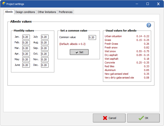
Albedo
In the Project Settings, you can define the far albedo, i.e. the albedo surrounding your site (the ground albedo right under the modules is defined in the System window for bifacial parameters).
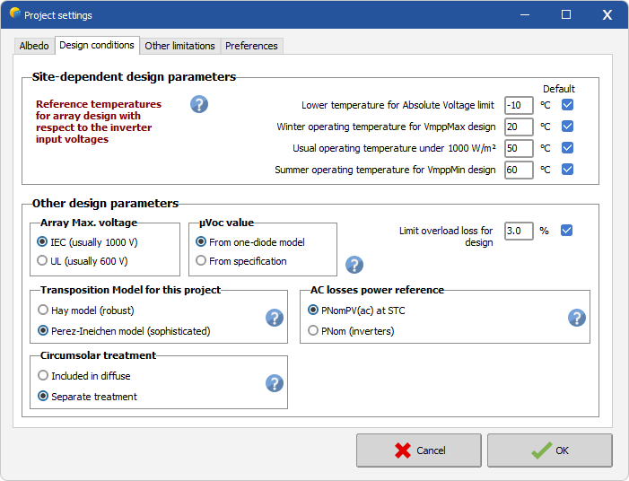
Design conditions
In the Site dependent design parameters, you can specify the minimum temperature expected at your site, in order to trigger a warning related to the absolute voltage limit. You can also define some reference temperatures for the design of the PV array, used to generate graphs in the sizing tool. (Note that the simulation itself uses the actual site data; these values are intended to assist in system design.)
In the Other design parameters, you find some options and values specific to the project itself. These are:
- Array max. voltage - It is a maximum admissible array voltage (Voc at minimum temperature), specified with the PV modules. The IEC standard requires 1000 V, the UL standard for use in the US is limited to 600 V.
- muVoc value - The Voc (Tmin) is normally calculated by the one-diode model. This option allows to use a derate factor muVoc specified by the manufacturer.
- Limit overload loss for design - The inverter sizing is based on an acceptable loss during the year, fixed at max. 4% by default. This parameter allows to increase this limit in order to define highly oversized PV array with respect to the inverter.
- Transposition Model for this project - Transposition is the calculation of incident irradiance on a tilted plane from horizontal irradiance data. PVsyst offers two transposition models
- Circumsolar treatment - Circumsolar irradiance is the part of diffuse irradiance coming from the region around the sun. For shading and IAM calculations, it can either be included in the diffuse component or treated separately. The separate treatment is the default in recent PVsyst versions
- AC losses power reference - AC wiring losses are calculated from the cable resistivity and the current flowing through the wires at each simulation time step. When defining relative ohmic losses, PVsyst offers two possible power references:
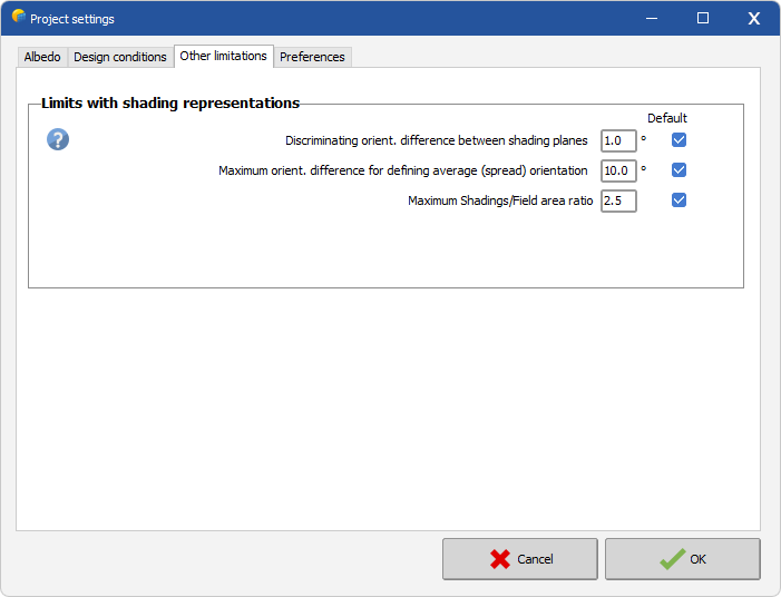
Other limitations
In the Other limitations tab, parameters can be defined related to thresholds used for shading analysis and for consistency checks between the 3D scene and the system definition.
- Averaged fixed tilt orientations: max. difference with respect to average - Defines the maximum deviation allowed between the orientation of each fixed-tilt table in the 3D scene and the averaged orientation used for the group. This tolerance is used to check whether the tables are compatible with an averaged-orientation definition.
- Maximum area ratio between 3D Fields and System modules - Defines the tolerance used when checking the compatibility between the module area defined in the System part and the field area defined in the 3D scene
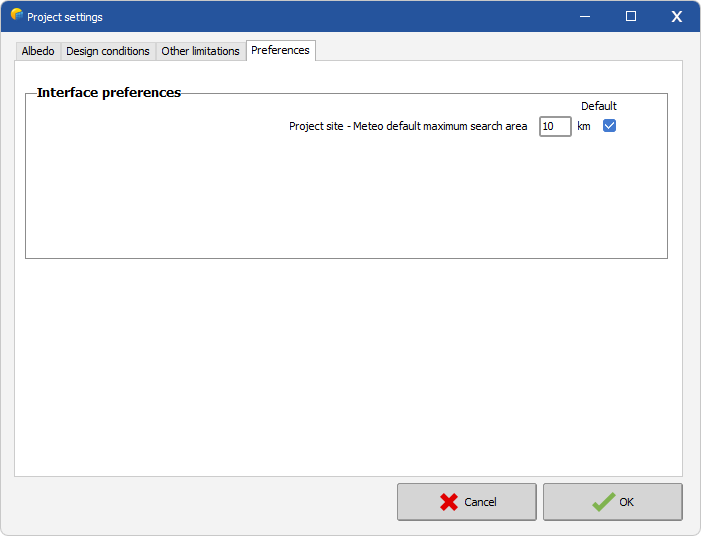
Preferences
In the Preferences tab, you can define the radius within which the program searches for meteorological data files around the project site. It is recommended to keep this value low to prioritize data representative of local conditions, and to increase it only if no nearby data is available.