Project design
This part aims to perform a thorough PV-system design and performance analysis using detailed simulations.
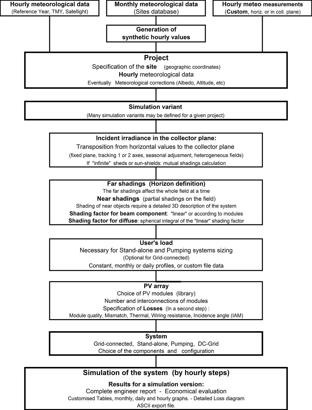
These are organised in the framework of a Project, which essentially holds the geographical situation and the weather data used for the simulation. Optimisations and parameter analysis can be performed through different simulation runs, called variants.
Procedure
NB: You have step-by-step tutorials to create your first project.
After choosing "Project Design" and the system type in the main window, the procedure is the following:
- First define the Project through the Project/Variant button. You can also retrieve an existing project through the
Filemenu. - For each Project (which includes geographic location, weather data, and optional albedo data), you can create different system variants as needed.
- For each variant, define the plane orientation.
- Define the System properties.
- The program verifies the consistency of all parameters and produces warnings in orange (acceptable for simulation) or red (preventing simulation).
- When ready (all parameters properly defined with only green or orange indicators), click the "Simulation" button. Red indicators or warnings indicate problems that prevent simulation.
- When simulation is complete, the "Results" dialog opens to view the main results on the "Report" document.
- After simulation, save each variant for further comparison (use "Save as" to avoid overwriting previous variants). Provide a descriptive name for each variant to easily identify it in the list and in your final report.
For a given project, first create a rough variant using all default parameter values.
In a second step, you can define the necessary refinements:
- In the "System" definition panel, you can modify the "Detailed losses" (soiling, IAM, module temperature parameters, wiring resistance, module quality, mismatch, unavailability, etc.).
- Optionally define a Horizon profile (far shadings).
- Near shadings—partial shadings from nearby objects, which require detailed 3D CAD construction of the PV field environment.
- Module Layout to describe the PV modules in the system for detailed calculation of electrical shading losses.
The following diagram shows an outline of the project's organization and simulation process.