Power Factor
Summary
In an AC circuit, power (or energy, when integrated over time) can be described by three main components:
- Active Power: This is the real power that performs useful work—such as generating movement or heat. It is measured in [kW], which are also sometimes written [kWac] in the specific context of discussing power factor.
- Reactive Power: A form of "virtual" power, created or absorbed by components like inductors (e.g., motors) or capacitors. It does not result in any net energy transfer. It is measured in [kVAr].
- Apparent Power: The vectorial combination of active and reactive power components. It is measured in [kVA].
In sinusoidal systems, these power contributions result from the phase shift between the current and the voltage waveforms. The so-called power factor defines the ratio of active to apparent power as $$ PF = \cos(\phi) $$
As well as converting photovoltaic output into active AC power, inverters can supply or absorb reactive energy. Grid operators may therefore request that PV systems supply reactive power to compensate for the reactive loads elsewhere on the network (motors, switched-mode power supplies, etc.).
Basic definitions
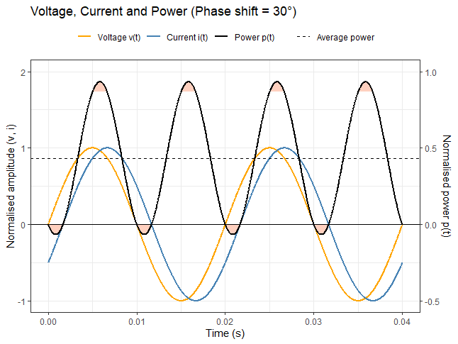 | 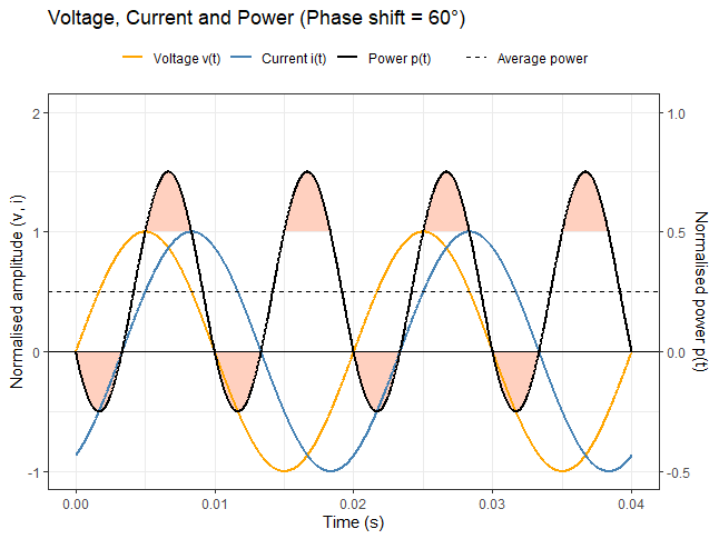 |
| Instantaneous current, voltage and power with a phase shift of 30° | Instantaneous current, voltage and power with a phase shift of 60°. |
In an AC circuit, current and voltage are time-varying waveforms. For a single angular frequency \(\omega=2\pi f\) the instantaneous current and voltage can be written
where the RMS value of a periodic signal is \(x_{RMS} \doteq \sqrt{\frac{1}{T}\int_{0}^{T}x^2(t)dt }\).
The phase difference between current and voltage \(\phi\) is positive when the current is lagging behind the voltage and negative when the current is leading in front of the voltage.
The instantaneous power is the product of the instantaneous voltage and current which reads
where we used some trigonometric formula in the last equality. The first term is time-independent (a “DC” term), whereas the second oscillates at \(2\omega\).
The average (real / active) power over one period is
where we note that the integral of the AC term over a full cycle is zero. Hence only the DC component transmits usable energy; the AC component alternates sign and transfers no net power.
A phase shift \(\phi\) therefore reduces the transferable power. This motivates defining the power factor (PF) as a measure of transmission efficiency:
Note that in the case of more complex waveforms, this definition of the power factor still applies. For our simple sinusoid we recover the familiar relationship
Apparent, reactive and active power definition
The previous time-domain derivation is intuitive but becomes tedious for arbitrary cases. Using phasors notation (complex number) is more convenient. In this framework, the waveforms are extended to the complex domain via Euler’s formula
Note that the normalisation factor \(\sqrt{2}\) disappears to keep the correct value of the RMS signal, which for complex waveforms is defined as \(x_{RMS} \doteq \sqrt{\frac{1}{T}\int_{0}^{T}x(t)x^*(t)dt }\), with \(x^*(t)\) the complex conjugate of \(x(t)\).
The so-called apparent power S is defined as
This quantity is constant in time and is directly equal to its time averaged. (Note the use of the complex conjugate of the current \(\check{i}^*(t)\) in that definition: using \(\check{i}(t)\) instead would result in a quantity with zero time average and therefore would not be very useful).
The real part of the apparent power is labeled as the active power P, which is the same as in the previous derivation,
and its imaginary part is labeled as the reactive power Q $$ Q = V_{RMS}I_{RMS} \sin(\phi). $$
As seen in the time-domain explanation, only active power delivers useful power. It is important to understand that reactive power cannot be used to produce movement, heat, or any tangible energy output. Conversely, reactive power can be generated without consuming any active power—as is the case with capacitors and inductors.
The relationship between apparent energy, reactive energy and active energy is therefore $$ S = P + iQ $$ often visualised as the right-triangle “power diagram”:
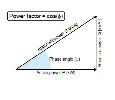
Within this framework the power factor is simply $$ PF \doteq \frac{P}{||S||} = \cos(\phi). $$ again measuring how effectively the apparent power translates into real, useful power.
Units in PVsyst
S, P and Q are all measureable quantities of a pair of signals \(i(t)\) and \(v(t)\). Electric utilities define rules that can apply either on active, reactive or apparent power. Despite all these quantities having units of power, pseudo-units are used in practice to differentiate their role in transmitting power. In PVsyst, they are naturally related to the apparent, reactive and active energy delivered to the grid (integrating those powers over time), for which we give the notation in the following table
| Quantity | Units | Related Quantity in PVsyst | Units |
|---|---|---|---|
| Apparent Power S | [kVA] | Apparent Energy transfered to the grid EApGrid | [kVAh] |
| Reactive Power Q | [kVAr] | Reactive Energy transfered to the grid EReGrid | [kVARh] |
| Active Power P | [kW], also sometimes [kWac] | Active energy transfered to the Grid E_Grid | [kWh] |
Reactive power produced by an inverter
The active energy produced by an inverter always originates from the input DC energy supplied by the PV array. Any real energy difference between the inverter’s input and output is converted into heat, representing the inverter's inefficiency.
Modern technologies such as Pulse Width Modulation (PWM) now make it possible to generate voltage and current signals with any desired phase shift—without additional energy cost. Traditionally, compensation is handled using large capacitor banks. The ability to generate such a phase shift results from explicit control within the inverter, defined by parameters in its control system.
For this reason, grid operators may request that PV systems produce reactive energy to help compensate for reactive power consumed by other grid-connected elements, such as motors or switching power supplies.