Simulation results
When defining a Power Factor, two new quantities are available in the results, the reactive and apparent energy exchanged to the grid. They will appear at the bottom of the loss diagram and in the advanced results.
The reactive energy delivered to the grid is computed at the inverter level from the available active energy at its output as
where \(\tan(\phi)\) is computed according to the requested power factor at a given time step of the simulation.
The apparent energy is then computed from the energy delivered to the grid at the injection point (i.e. from the active energy fed to the grid) as
The apparent energy is obviously always superior to the active energy.
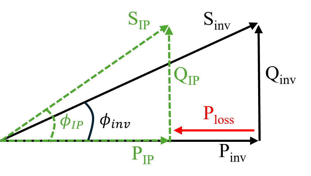
Modification of the power factor between invert output and injection point
Note that PVsyst assumes no loss of reactive energy between the inverter's output and the injection point. The reactive component is computed at the inverter level and is not modified further downstream, arriving at the injection point unaffected.
Therefore, if some active energy is consumed or produced in between (e.g. from self-consumption or from battery storage), the effective angle between the active and apparent energy at the injection point might be modified with respect to the requested power factor set at the inverter. This is illustrated in more details in the figure and sections below. Here we show how the power factor is modified between the inverter output and the injection point when there is an active power loss in between. Note how the apparent power is the vector sum of active and reactive power at a given point of the system.
An effective yearly \(\cos(\phi)\) value delivered to the grid is also given in the loss diagram along the reactive energy. It will typically differ from the requested power factor in the following cases.
Power Factor and Self-Consumption
In PVsyst, self-consumption consumes only active power. Since the reactive energy is not affected, the effective power factor delivered at the injection point increases with respect to the its value at the inverter output.
Power Factor and storage
The battery stores and delivers only active power. Therefore the power factor can increase or decrease at the injection point momentarily. However, averaged on a battery cycle, the power factor can only decrease as the charge/decharge steps add additional losses of active energy.
Power Factor and Grid limitation
The grid manager may ask for a limitation specified in apparent or in active power. This can be set in the tab Grid Power Limitation. The presence of a grid limitation acts as inverter clipping, being applied before the inverter output point. The reactive power is therefore following the clipped active power (multiplied by \(\tan(\phi)\)) and the power factor at the injection point is unaffected by the grid power limitation.
NB: some grid limitation requirements are based on a specific state of the Grid (especially the grid voltage). Taking such requirements into account is not possible in a PVsyst simulation at the moment, as it would require knowing the Grid voltage at each time step, as an input parameter.
Resistive losses on the AC side
Consider the inverter as an upstream source that must deliver active power \(P_{\text{inv}}\) through a series resistance \(R\) (cables + transformer) to the grid-injection point, whose RMS voltage is \(V_{\text{RMS}}\). For a commanded power factor \(\cos\phi\) at the inverter level, the required RMS current is
The ohmic loss between inverter and meter is therefore
so the losses grow with the factor \(1/\cos^{2}\!\phi\) compared with the unity-PF case.
The active power that actually reaches the grid is
and is therefore reduced.
Three-phase systems: replace \(V_{\text{RMS}}\) with \(\sqrt{3}\,V_{\text{LL}}\) (line-to-line RMS voltage) and, if \(R\) is the per-phase resistance, multiply \(P_{\text{loss}}\) by three. The \(1/\cos^{2}\!\phi\) dependence remains unchanged.
Limitation in PVsyst
PVsyst does not yet model impedance-related losses (especially inside the transformer).
The software assumes that the reactive energy is the same at the inverter terminals and at the grid injection point, and only the active energy is reduced by the user-defined AC ohmic losses. Consequently the power factor calculated at the point of injection will be slightly lower than the power factor at the inverter output, similarly as in the self-consumption scenario.