Multi-MPPT inverters
Many inverters have multiple MPPT inputs. These inputs can function as semi-independent inverters. This multi-MPPT option can be defined in the inverter definition using the "multi-MPPT capability" setting.
PVsyst considers two types of Multi-MPPT inverters: normal and unbalanced. These models are described in detail on the inverter model page.
Normal Multi-MPPT inverters can be defined either as a whole ("Pnom sharing within the inverter") or as "independent MPPT inputs". "Unbalanced" inverters are automatically set to "independent MPPT inputs".
When "Independent MPPT inputs" is selected, you must specify the number of MPPTs instead of the number of inverters. The number of inverters shown in the List of sub-arrays summary is automatically updated based on the number of physical inverters with MPPTs connected to this sub-array.
In PVsyst, a sub-array is, by definition, homogeneous: all strings have the same PV module model and number of modules in series. With the "Independent MPPT inputs" option selected, it is possible to connect strings from different sub-arrays to the same physical inverter. To do this, you must define two sub-arrays with the same inverter model and "independent MPPT inputs" selected.
This example shows two different sub-arrays, each connected to one MPPT input of a two-MPPT inverter: 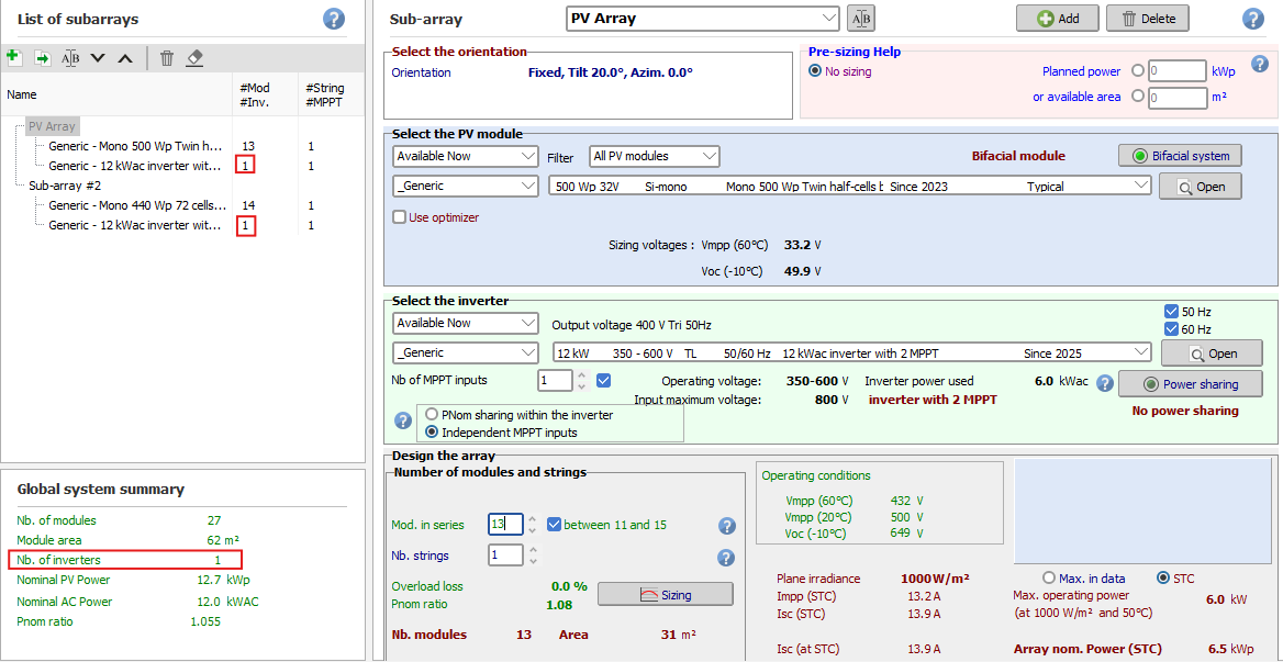
In this example, in the List of sub-arrays, each sub-array is assigned one inverter. This value, always an integer, indicates the number of physical inverters connected to the sub-array. In the global system summary, Nb. of inverters is also 1, meaning the global system has only one physical inverter total. The Power Sharing button, visible on the right, allows additional configuration options. These options are covered in the Power sharing page.
Normal Multi-MPPT inverters
The vast majority of multi-MPPT devices have identical electrical requirements for each MPPT input.
By default, PVsyst assumes that an inverter with n MPPT inputs behaves as n identical inverters of 1/n the total inverter nominal power. This is not a problem as long as you do not have overload losses—that is, when each sub-array has an acceptable power ratio (less than 1.25 to 1.3).
However, during operation, real inverters can dynamically share the total output nominal power among their different MPPT inputs. PVsyst can account for this PNom power sharing in different ways.
NB: If all MPPT inputs of an inverter are not used, PVsyst assumes only a fraction of the inverter is available. For example, a 10 kW inverter with two MPPTs, where only one is used, will have a maximum output power of 5 kW if "Independent MPPT inputs" is selected.
Inverters with unbalanced MPPT inputs
Some specialized inverters (such as those in the Tripower series of SMA) have 2 MPPT inputs with very different power ratings. In practice, this is very useful: you can define an array without many constraints on the module number on the main input, and use any remaining modules on the secondary input, regardless of their number. This feature is part of the inverter definition.
With these very special unbalanced inverters, when defining a sub-array, you can choose between "Main" and "Secondary" MPPT inputs.
In principle, you should define sub-arrays using the same number of "Main" and "Secondary" inputs (i.e., use all available inputs). However, the Adjust button allows you to skip using the secondary input. Please check with the manufacturer to verify this is possible with your actual inverters.
At design time, the nominal powers of each input are evaluated according to the maximum currents specified for each MPPT input. This may sometimes lead to unacceptable overload losses. If this warning is red (error), you must increase the allowed overload energy loss in the "Project" parameters (Albedo-Settings).
At simulation time, power sharing (as mentioned above for normal MPPT inputs) is automatically performed based on the PV modules connected in each sub-array. The Pnom of each MPPT input is evaluated just before the simulation.
Example of use (tutorial):
Suppose you need to build a PV system using 155 PV modules of 250 Wp—that is, 38.75 kWp.
- Choose the inverter(s) according to a reasonable PNom ratio of 1.25: you need inverters for PNom(ac) = 38.75 kW / 1.25 = 31 kW. Two inverters with unbalanced MPPT, of PNom = 15 kW each, would be well suited.
- In the "System" section, define 2 sub-arrays.
- First, define the "Main" input with 6 strings of 20 modules (120 modules total) using 2 "Main" inputs: you get a PNom ratio = 1.25, which is correct.
- There are 35 modules remaining to be assigned. This corresponds to 2 different "Secondary" inputs, so increase the number of sub-arrays to 3.
- Sub-array #2: define 1 "secondary" input and assign 18 modules.
- Sub-array #3: define 1 "secondary" input and assign 17 modules.
- Now the warning "The inverter power is strongly undersized" appears in red because the overload loss exceeds 3% (depending on weather data). You must increase the "Limit overload loss for design" in the project definitions.
Your system is now ready for simulation.