Grid storage, system architecture
PVsyst architecture
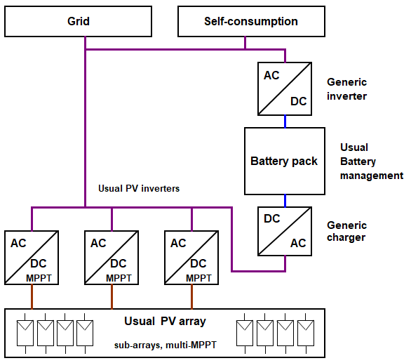
In PVsyst, for all strategies the PV system is defined as a standard grid-connected system, with usual solar inverters.
The battery pack is unique (centralized). Charging is provided by an AC-DC charger connected to a common AC bus at the inverters' output. The stored energy is delivered by a DC-AC inverter to either the grid or the possible self-consumption load.
The DC-AC inverter is quite different from typical PV inverters. It is a "battery-inverter" type device. The power source is the battery pack, which can deliver any power at any time (within battery constraints), independent of solar availability. The operating power must be explicitly controlled, either by user demand and/or activated when necessary for grid supply.
For very large systems, there may be several charging devices connected to different sub-systems. However, PVsyst defines only one generic AC:DC charger, characterized by a maximum power and efficiency, for the entire system.
Direct coupling of the battery pack
Some people want to avoid the two transformations (DC(MPPT)-AC solar inverter + AC-DC charger) and use direct feeding of the battery pack from the PV array.
However, this is not straightforward.
If you need to control the power sharing between direct use and battery charging, it is necessary to have a centralized connecting point, receiving the Solar energy from the array (when available), and distributing to the direct use or DC storage (controlled strategy)
This applies in all cases, including the peak shaving option, where only the excess power (of the full system) is stored. Because overpower is a global characteristic, it obviously does not make sense to define some sub-arrays with DC:AC inverters and other sub-arrays feeding DC-DC converters.
There are only three solutions for achieving a centralized point:
- You share the PV power at the array level. This requires to define one only array for the full system.
- You define a common DC bus for AC and DC production. This bus may be directly connected to the battery pack, or through a DC-DC converter.
- Some inverter manufacturers provide inverters where the internal DC bus (between the MPPT inputs and the DC-AC output) is externally available for feeding DC-DC converter.
- The common bus is the usual AC output of the system. This is the solution presently involved in PVsyst.
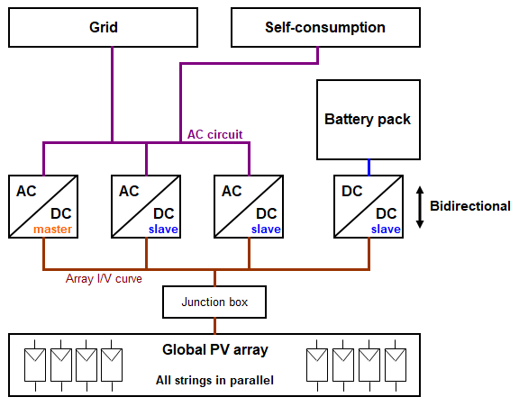
A - Sharing the PV array
This is only possible by defining a single PV array, meaning all strings of the system are connected to one point.
In this case, when several conversion devices are connected to this array, you should use the "Master/Slave" strategy. At any time, one inverter defines the maximum power point voltage of the full array (the "Master") and transmits this MPP voltage information to all devices connected to the PV array. Moreover, the master must decide and control the power directed to the DC-DC converters charging the battery pack.
This obviously prevents using multi-MPPT inverters and requires non-standard inverters capable of operating in "Master/Slave" mode. The DC-DC converter for charging the battery pack must also be able to operate in voltage "slave" mode with controlled power.
For large systems, the currents may be prohibitive. For a 1 MW array operating at Vmpp = 1000 V, the "Master" must control the full array with a current of 1000 A.
You can, of course, split the main array into several sub-arrays. In this case, each sub-array must be equipped with a master inverter and a slave DC converter.
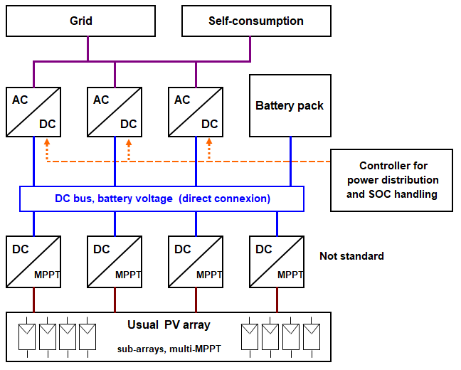
B - Common DC Bus
This requires MPPT-DC converters to transfer solar energy from the PV array to a common DC bus. Standard PV strategies with small sub-arrays and possible multi-MPPT inputs can be used. However, such devices are not standard in the market.
The DC bus power must feed DC-AC inverters with a fixed voltage input. Again, this does not use standard devices. In addition to using a fixed input voltage, external control must specify the power at which this inverter must operate at each time step.
There may be 2 kinds of DC bus:
- The DC bus is directly connected to the battery pack—that is, at the battery voltage. You should verify whether this mode is compatible with the BMS control system of the battery pack.
- One advantage of this mode is that you can use the same inverters for both charging and discharging the battery.
- This mode is the only one that allows saving one conversion when charging and discharging the battery. However, the operating power flows must be closely linked to the battery state of charge, as in a stand-alone system. A central control should operate the same way as a controller in a stand-alone system.
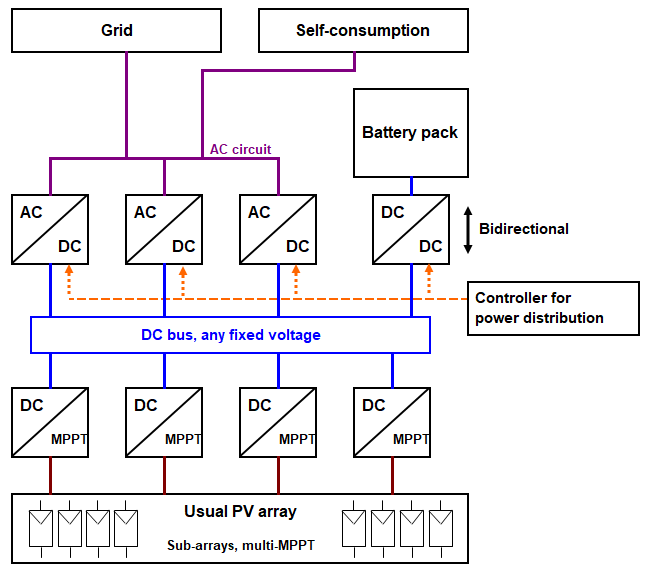
- The DC bus is connected to the battery pack via a DC-DC converter. This mode requires a bi-directional DC-DC converter to also ensure battery discharge to the DC bus. In this situation, you have the same number of conversions as in the AC-coupled case: when charging, you have 2 DC-DC conversions, and when discharging, a DC-AC followed by a DC-AC conversion.
- However, the involved devices are much less standard, and the control is significantly more complex than with the common AC bus.
C - Common AC Bus
This is the situation implemented in PVsyst and described above.
This architecture uses mostly standard devices (including DC-AC and AC-DC converters often included in battery packs) and can be easily integrated into a standard PV system without major modifications. Only the control system requires modification.
With appropriately designed inverters, this mode can also serve as a "backup" battery installation to supply internal loads in case of grid failure.
This is not possible with typical solar inverters, as they require the grid to be present for operation. Remember that safety regulations require the inverter to stop operating as soon as the grid is disconnected (no islanding).
Defining your own configuration in PVsyst
If you have an architecture different from the PVsyst model, you can still evaluate its performance by defining suitable efficiencies for the input and output storage parameters. You should simply verify that the efficiency of your configuration's converter chain is equivalent to the efficiency in the PVsyst simulation—that is, the inverter efficiency multiplied by the AC-DC charger efficiency. The overall system behavior cannot be significantly different if you have a DC converter before the inverters.
The main result expected from the simulation relates to the overall energy flows over the year (available PV power, dispatch to the grid, and stored powers). The balance of these flows at any time is much more important than the details of efficiencies at a given moment.
NB: These considerations stem from theoretical reasoning. If you design a real architecture that contradicts the statements above, please send us a detailed description so we can possibly correct or update the assertions mentioned here.