Bifacial systems procedure
Please also read the Bifacial model principles. To define a bifacial PV system:
1. System layout
The current bifacial model in designed for large, regular systems with fixed planes or trackers. The modelling of the backside irradiance, currently is done based on a 2D cross section representation of the system, akin to unlimited sheds or unlimited trackers, with simplifications such as neglecting edge effects at the ends of individual tables and the first and last table at the boundaries of the overall array.
To apply to the 2D model conditions, you need to define a system with a regular pitch, table size and orientation. These parameters can either be defined using the 2D unlimited sheds and unlimited trackers field type in the orientation window, or to define row arrangements of _fixed tilt tables and single axis trackers in the _3D scene__. A system defined in the 3D scene must be sufficiently regular to allow for a valid 2D cross-sectional approximation for the modeling of backside irradiance.
Warning
While PVsyst can perform bifacial calculations with multiple orientations and mixed orientation sub-arrays, the necessary assumptions do not currently permit modeling bifacial EW fixed tilt systems. Mutual shadings between orientations are indeed neglected. Note that most of these systems (barring carports) have very little backside irradiance.
2. PV module choice
In the System window, you have to choose a PV module specified as Bifacial to define a bifaciality factor.
When choosing such a PV module, the button Bifacial system will appear just above the PV module definition. This opens the following window, with the general parameters related to a Bifacial system.
- Bifacial model
- Disabled : No bifacial computation will occur, even if bifacial modules are selected
- Unlimited shed / trackers : The bifacial computation will be based on this "orientation" model
- Ground Albedo
- None : Disable the bifacial model
- Constant : same value for the whole year
- Monthly : allows different value each month
- From file : Use a timeseries to defined a hourly or subhourly ground albedo value
Info
Mixed orientation sub-arrays have two orientations, hence two independent bifacial models must be defined. A drop down menu at the top of the "Bifacial system" window allows to define each of these.
Info
Multiple sub-arrays with the same orientation will share their bifacial model. Activating the bifacial in one of them is therefore sufficient.
3. Main bifacial parameters
Once you have selected the model according to your orientation, a dedicated tab will open.
Model Pages (unlimited sheds or trackers 2D models)
This opens the corresponding page, where the basic geometric parameters are predefined according to the orientation or its 3D layout.
In the Orientation section in this window, you can play with the parameters to analyze the effect of different configurations. However, when exiting this page, the parameters will be reset to their default values based on your system definitions.
In the Sheds/Trackers and Ground Parameters section, values for pitch, table/tracker width, and the number of rows are suggested based on the defined system layout. If you have created a 3D scene and find that PVsyst has not accurately calculated the values for the pitch and number of rows, you have the option to manually override these values. Note that the number of rows refers to the number of rows in the 2D cross-sectional representation of the system, assuming "unlimited long tables", and is relevant for the calculation of the effect of the first and last row of the array.
| Height above ground | the only parameter without correspondence in the system's definitions is the height above ground that you have to define here. This is the height of the bottom of the sheds or of the axis in the tracker case. |
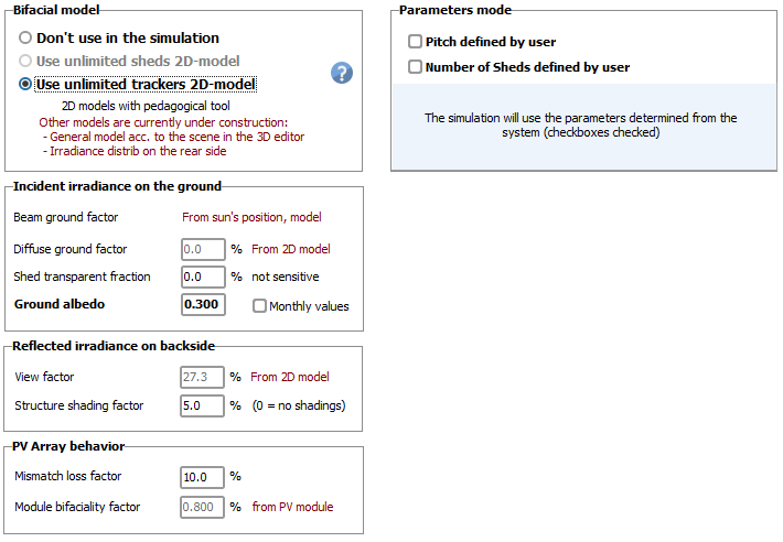
General Simulation Parameters page
Among the parameters on the general parameters page, several are fixed by other calculations:
| Beam ground factor | is the fraction of the Beam on horizontal plane reaching the ground between the tables. This evolves according to the sun position and depends on the weather data. This is not really a parameter, but an indicator. |
| Diffuse ground factor | is the fraction of the Diffuse on horizontal plane, as seen by each point of the ground (integral over all directions). This depends on the system geometry, the average of all contribution ground points is given here. In tracking systems, this depends on the tracker's position. |
| Reemission form factor | represents the fraction of the irradiance from ground reaching the back side of your system. This is calculated as an integral for each point on the ground, and you have here the result of the average from the model. This only depends on the geometry. For tracking systems, it depends on the tracker's position. This is an indicator calculated from the model. |
| Module Bifaciality factor | is the ratio of the rear side yield under STC, with respect to the front side STC performance. This is a specification of the PV module. |
Other parameters are instead to be fixed by the user:
| Shed transparent fraction | describes how much light can pass through a row of modules, and reach the ground beneath (i.e., contributing to the ground irradiance). It should include spacings between cells (if transparent) and spacing between modules (if transparent). You can also use this parameter as an approximation if you have some spacing between tables, provided that this is not too large. This parameter is usually null except for spacing between tables. |
| Ground albedo | is the albedo property of the ground below your system, contributing to the bifacial reflection. This has nothing to do with the albedo defined in the Project, which characterizes the (far) terrain in front of your installation. This parameter may be defined in monthly values to take the eventual snow into account. |
| Structure shading factor | represents the loss of irradiance due to the structure shading the rear side. As a first approximation, this could be estimated as the ratio of the area covered by structures to the photovoltaic area. In this approximation, the effect of structures is therefore their projection on the rear plane. Therefore, it neglects the fact that light may arrive on the rear side from multiple directions, akin to diffuse light. This approximation is hence likely an underestimate of the shading loss, in full generality. Indeed, even if structural elements are not directly in front of the rear side of modules, they may cause significant shading. A better approximation is beyond the present possibilities of PVsyst. We therefore recommend using the default value (5%) for structures adapted to bifacial modules. Such structures avoid covering the rear side of modules. The default value has been indirectly validated by comparing PVsyst simulation results with measurements in the context of bifacial systems. In the case where structural elements or other obstacles are partially covering the rear side, however, the projected area approximation becomes a better approximation, especially when it exceeds the default 5%. |
| Mismatch loss factor | is caused by a heterogenous irradiance distribution on the rear side. Any source of heterogeneous irradiance will cause electrical mismatch effects. Such is the case of shading cast by structural elements, but also differences in location relative to the environment and the ground. For example, the uniformity of the rear irradiance will increase with the height above the ground. Other contributors to the mismatch effects are electrical layout considerations and the amount of irradiance on the front side. At present, PVsyst has no easy way to make an accurate estimation for these effects. Based on comparisons with measurement data, we have determined a default value (10%), which should be recommended for most cases. As with the shading factor, in case where the structural elements are directly in front of the rear side of modules, the mismatch losses may increase drastically. In such a case, one can roughly estimate the mismatch effect as follows: as the current in a string is the current in the worst cell, if the structure covers x% of one cell, the shading effect will be x% for the concerned string. For example, the loss may be reduced by a factor of 2 if the structure covers half a cell (or two half cells). |
These parameters are all part of a bifacial model, therefore they are defined for a given orientation.