Temperature behaviour correction
In the standard one-diode model, the temperature behavior is essentially determined by the dependency of the diode saturation current Io:
i.e. with a cubic and exponential temperature dependency, as well as a dependency on the Egap and Diode Ideality factor Gamma.
This expression fixes the muVco and muPmax temperature coefficient values, which are therefore a result of the model.
Temperature Correction on Gamma
Remember that the gamma value (diode ideality factor) is one of the 5 unknown parameters of the one-diode model, determined (or assumed) in correlation with the Rseries choice, which can vary from 0 to Rseries Max.
The muVco and muPmax resulting from the model are not necessarily the same as the manufacturer's specifications. Therefore PVsyst allows for modifying the temperature behavior of the model by introducing a linear variation of Gamma with operating Temperature:
In the PV module definition dialog, page "Model parameters" / "Temper coeff.", the user may specify a required muPmpp value, and PVsyst will determine the suited "muGamma" correction factor.
For crystalline modules, the model represents reality quite well, so the correction is typically very small (rarely above 0.03–0.04%/°C).
With the amorphous and other thin film technologies, the temperature coefficient is very sensitive to the d2MuTau parameter. According to our detailed measurements, cumulating this correction with the recombination leads to degraded performances of the model (that is, its ability to reproduce the data in any conditions). However when defining parameters for such modules in the database, this parameter is used for a final fit o the specified muPmpp value and may be up to 0.12%.
NB1: The tool shows a graph of the induced variations on muVoc, muVmpp and muPmpp. According to the one-diode model, the muVoc and muPmax coefficients are not constant; they themselves vary with temperature. Therefore, applying manufacturer values established at 25°C as constant derate factors is not necessarily accurate.
NB2: The curves may sometimes show discontinuous behavior at very low temperatures. This is due to a computational limitation: as shown in the above expression, the Io temperature dependency is very significant. With some modern modules (very high fill factors), IoRef at 25°C becomes very low, and the exponential calculation leads to picoamp fractions, for which we had to set a lower limit. This discontinuity corresponds to the computational limit.
muVco temperature coefficient
Externally specified muVoc and muPmax temperature coefficients cannot be reproduced simultaneously by the one-diode model. When we adjust muGamma to achieve the desired muPmax behavior, muVoc is fixed, not necessarily to the manufacturer-specified value.
Accurate (or specified) Voc behavior as a function of temperature is not truly necessary during simulation: no energy is produced at Voc.
However, the coefficient muVoc is used during system sizing to determine the maximum voltage potentially attainable by the PV array under worst conditions (i.e., the lowest temperatures ever encountered). This safety test is required during PV array design, and the PVsyst value (from the model) sometimes results in higher Voc(Tmin) than design software using the specified muVoc.
This is the reason why the PVsyst database now allows to store the muVco value specified by the manufacturer (only available for some few modules in the present time). And in the project's definition (Project's Settings), you can choose to use this value instead of the PVsyst value during your design.
Details about the muPmpp determination
According to the measurements reported by the specialized laboratories, the maximum power point Pmpp behaves very linearly with the temperature.
The muPmpp parameter specified by the manufacturers is the slope of this linear dependence.
Now the Pmpp temperature dependency as calculated by the one-diode model is not exactly linear:
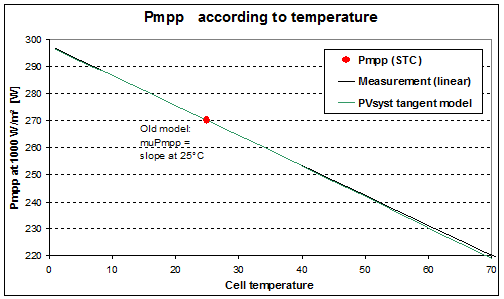
When this little discrepancy is not really visible here, we may draw a plot with a zoom on the real behaviour:
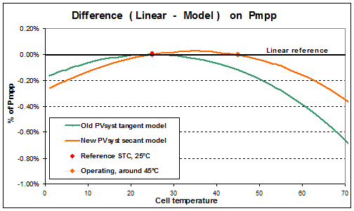
Until version 6.25, PVsyst adjusted the slope to achieve the correct slope at 25°C (that is, a tangent adjustment). Under these conditions, the deviation is approximately –0.03% at 35°C, –0.12% at 45°C and –0.28% at 55°C relative to the linear hypothesis.
Since version 6.26, PVsyst uses the slope corresponding to the secant between 25°C and 45°C. This improves model accuracy at actual operating temperatures and results in a reduction in temperature loss of approximately –0.1 to –0.2% (of annual yield) for typical PV systems (depending on climate and thermal U-factor).