Submodules
In PV modules, cells are typically connected internally in series.
This means that cell voltages are added, and the PV module voltage is the sum of all cell voltages:
\(V(Module) = V(cell) * NCells in serie\)
SubModules
However, a large series like this can lead to a hot-spot effect if one cell is deficient or shaded. If a high current is imposed, the deficient cell may be forced to absorb all the power produced by the cells in series with it, which can damage the cell.
This is why we install a "bypass diode"—a reverse-biased diode that can bypass the reverse current that might be imposed on the series string. In this case, the damaged cell only needs to absorb the power produced by its section of cells.
In practice, the maximum safe number of cells for hot-spot protection is approximately 20 to 24. Therefore, every PV module has a partition into cell groups, each protected by a bypass diode. These groups are called sub-modules.
The Submodules Layout parameter in the PV module definition describes the distribution of submodules..
Electrical shadings
Therefore the main objective of the By-pass diode is to protect the PV module.
Bypass diodes also affect electrical shading losses. Sub-modules are indeed the basic unit for analyzing electrical shading losses in an array. Regardless of how many cells are shaded in a sub-module, the resulting I/V curve of the full sub-module is nearly identical. Only the Pmpp voltage differs slightly, but in an array, shaded sub-modules or strings rarely operate at MPP.
Therefore, when analyzing or constructing the I/V curve of a shaded array, the "Module Layout" tool works only with sub-module characteristics (shaded or unshaded). Individual cells can be ignored.
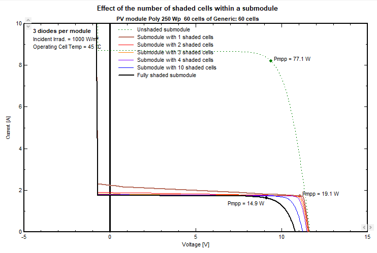
This plot is available in PVsyst Tools > Electrical behaviour of PV arrays > Array with shaded cells.
Here you can choose "Number of shaded cells effect > One sub module".