Determination of parameters
Determination of the model parameters
For a reference temperature and irradiance (\(G_{Ref}\), \(T_{Ref}\)), we have now a model based on 5 unknown parameters.
Let us recall the basic equation, where the variables are written in blue and the 5 unknown parameters in green:
We can explain intuitively the different components of this equation:
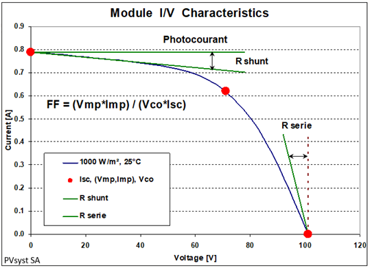
- The IphRef value (photocurrent) is constant, whatever the voltage.
- The Rshunt current loss (component (V + I · Rs) / Rsh)) obeys ohm's law: this is a linear increase of current as function of voltage.
- The Rseries is a voltage drop between the internal cell voltage (V+I·Rs) and the voltage applied to the external load. This voltage drop also obeys the ohm's law.
- The difference between Rshunt and the blue exponential is the exponential current in the diode (simplified: \(I_{0,ref} · exp (q·V/N_{cs}·\gamma·k_B·T_c)\) term).
NB: The Rseries defined within this model is not the inverse of the slope of the I/V curve around Voc. There is a contribution of the exponential.
If we avail of a full I/V curve measurement
The Rshunt is simply the inverse of the I/V curve around the point (V = 0, ISC). Therefore it is considered as known, and fixed in the equations.
Therefore we have still 4 variables to be determined.
From the reference I/V curve measurement, we can extract the quantities IscRef, ImpRef, VmpRef, VocRef.
We may write the basic one-diode equations at the 3 known reference points: (0, ISC), (Vmp, Imp), (Voc, 0). The (Vmp, Imp) exact voltage position is not important. It may be "around" the maximum point. This gives 3 independent equations.
As we have 4 variables, for solving this system we have to fix one of the variable at an arbitrary value, so that there are 3 remaining parameters.
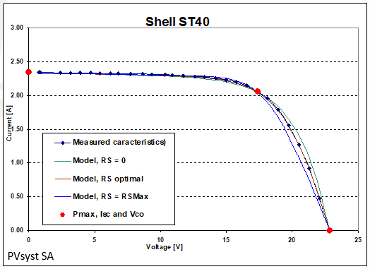
We start by setting Rseries = 0. We solve the system and get a set of parameters, which allows to get the I/V curve for this situation.
Then we incrementally increase the fixed Rseries and resolve the system. We continue until the system no longer has a solution. This limit resistance will determine a value which we name RSMax, the maximum series resistance.
The actual Rseries should lie between these two values. We can adjust it by finding the I/V curve that best matches the measured points.
 | 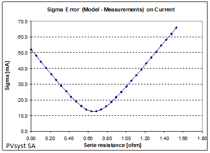 |
| RMS difference between Measured values and model The minimum is often as low as 0.4% of Isc for good measurements. |
All curves always pass through the 3 reference points: this is normal, as the solutions are based on the equations written at these 3 points.
If we avail of the Manufacturer's datasheets only
In this case we don't have the full I/V curve, and therefore we have to find another way of defining the Rshunt and Rserie values.
For Rshunt, we choose an initial arbitrary value: Rshunt = Vmpp / (0.2 * (Isc - Impp)). See more details here. This value limits the RsMax, and may be increased afterwards when necessary (i.e when the target low-light efficiency cannot be reached).
For Rseries, we do not have sufficient information at this stage. We will see later that the Rserie is strongly related to the low-light performance: its value will be fixed according to the measured (or supposed as default) low-light relative efficiency.
Reverse part of the Characteristics
Some tools in PVsyst - namely in the study of Shading or Mismatch in arrays - require the knowledge of the reverse characteristics, when a negative voltage is applied to the module (region V < 0).
This model is not as well determined in PVsyst as the direct characteristics (see Reverse characteristics modeling), but this description is sufficiently detailed to understand the behavior shown in the related tools. The effect of the real behaviour is marginal in the I/V characteristics of partially shaded PV modules.