Inverter model: multi-MPPT
Multi-MPPT inverters
Many inverter models have several MPPT inputs, each usually with identical specifications.
During simulation, PVsyst treats a multi-MPPT inverter as several independent identical inverters. For example, a 10 kW inverter is equivalent to two 5 kW inverters.
With this approach, if you connect different numbers of PV modules to each input, overload losses can occur on one input but not the other. In real multi-MPPT inverters, the limit applies globally; nominal power can be shared between inputs.
Since PVsyst version 6.33, this behavior can be accounted for by manually specifying PNom for each input, provided the total equals the inverter's Pnom.
See Multi-MPPT inverters use in sub-arrays.
Unbalanced MPPT inputs
Some few special inverters have two different MPPT inputs: one for the main part of the modules, and one receiving a single string with any number of modules (within the voltage limits). This is a very interesting configuration, as it allows to connect virtually any number of modules to a single inverter: the "Main" inputs has a homogeneous product (for example 3 x 20 modules), and the "Secondary" receives the rest of the modules to be installed.
In PVsyst, these inverters are specified as unbalanced MPPT inputs and are treated in a specific way.
PVsyst defines main and secondary inputs (only 2 possible), specified by maximum current (secondary current typically suits a single string of 6" cell modules).
At design time, PNom for each input is shared based on the maximum current specified for each input.
At simulation time, PNom is reassigned based on PV module power actually connected to each input. This prevents "asymmetric" overpower losses.
See Multi-MPPT inverters use in sub-arrays for details.
Master/Slave operation
Master/slave operation is a feature of a few specialized inverters.
In this mode, the array is connected to the inputs of 2 inverters, but only one of them (the Master) is performing the MPP tracking on the array, and transmits information to the second one (the Slave).
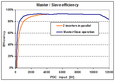
The master operates alone until array power exceeds a threshold (typically its own PNom), offering better performance at low powers. Efficiency gain may reach 1-2%, less with modern high-efficiency inverters. The global efficiency curve is improved as follows (example: two 5 kW inverters):
NB: Many large MW-range inverters are actually assemblies of 100-200 kW units operating in master/slave mode internally. Externally, this improves the efficiency curve (which has a sharp low-efficiency knee). However, simulation treats these as single conventional inverters.
Connection of the PV array to the inverter
Be careful: As a general rule, never connect multiple MPPT inputs in parallel; each should be an independent circuit to avoid MPP tracking conflicts.
Conversely, in master/slave mode, the array must be connected to both inverter inputs so each inverter sees the entire array.