|
<< Click to Display Table of Contents >> Module Layout Electrical definition |
  
|
|
<< Click to Display Table of Contents >> Module Layout Electrical definition |
  
|
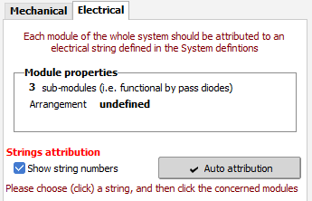
The aim of this page (tool) is to associate a string (specified in the Sub_arrays of the "System" part) to each module on the tables.
This is only possible after a correct definition of the "Mechanical" parameters.

Strings list
On the left panel, you have a list of all inverter (or MPPT) inputs as defined in the sub-arrays.
Each string is represented by a set of PV modules, of different colors according to their number (colors 1..10).
In this example we have 5 strings per Inverter, and 16 modules per string.
Modules distribution
On the tables drawings, each module is associated to a string. The color - and a possible string number appearing when the modules are sufficiently large - identifies the corresponding string.
Colors
The colors are those characterizing the electronics components (except 9 and 0):
1 = brown, 2 = red, 3 = orange, 4 = yellow, 5 = green, 6 = blue, 7 = violet, 8 = grey, 9 = purple, 0 = dark grey.
Objective
In a rows (sheds) or trackers arrangement, the optimal distribution of modules is to allocate all modules belonging to a same string to a single row in the table.
This way all modules of one string will be shaded identically. This is the best situation for the row-to-row shading losses.
Also, usual modules with 3 sub-modules in length should be positioned in landscape, when twin half-cut cells modules should be in portrait.
|
|
Orientation
If there are several orientations in the system, each orientation has to be managed independently.
You can choose the working orientation using a combobox.
On the right panel, you will see exclusively the tables of the chosen orientation. The orientation of each table is clearly defined in the 3D scene.
On the left panel, you always see all inverters. Each inverter input corresponds to a sub-array, and is therefore associated with the orientation of this sub-array. The inverter inputs not corresponding to the chosen orientation will appear as desabled: you cannot of course associate modules of thie view to them.
When using mixed orientation in a sub-array, only strings corresponding to the chosen orientation will be enabled.
NB: When defining domes, both tables will be shown on the geometrical view on the right. In this case the direct or opposite table will be enabled, according to the chosen orientation.
Manual association of modules to strings
A simple way of associating each module to a string is to choose (click on) a string on the left, and then click the modules to be assigned (you can move the mouse on several concerned modules). You can un-assign a module by right-clicking. The colored cases on the left correspond to the number of assigned modules. The blank cases indicate the number of modules still to be attributed.
This way is obviously cumbersome with a big system.
Manually moving or exchanging the assignments
As an option (click icon on the right), you can enable a mode in which you displace the string assignment of a module to an unassigned module, or exchange it with another module, simply by dragging it. This may be useful when you have finished the automatic attribution, and you want to perform some adjustments.
Automatic attribution
For big systems, the button "Auto Attribution" opens the dialog explained on the next page.