|
<< Click to Display Table of Contents >> Master Slave Operation |
  
|
|
<< Click to Display Table of Contents >> Master Slave Operation |
|
The simulation is able to treat the Master/Slave operation.
In this mode you have to define the number of slaves (for ex. 1 slave for one master and one slave, 2 slaves for one master and 2 slaves).
If your sub-array doesn't use the Master/Slave feature please put NSlaves = 0.
Principle
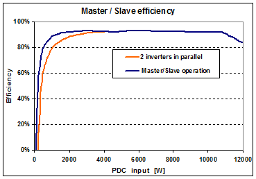
In this mode, the array is connected to the inputs of 2 (or several) inverters, but only one of them (the Master) is performing the MPP tracking on the array, and transmits information to the second one (the Slave).
The Master begins to operate alone, until the array available power overcomes a given threshold. Therefore, as seen on the graph, it operates better under low powers.
The gain may be of the order of 1 to 2% maximum, lower with modern high-efficiency inverters; therefore very few modern inverters are supporting this mode.
Wiring
In normal (not M/S) operation you should always connect the MPPT inputs independently (i.e. one array - set of strings in parallel - on one MPPT input), and never interconnect MPPT inputs unless there will be MPPT tracking conflicts.
As a contrary, in Master/Slave operation both inverters should "see" the full array, that is you should connect the inverter's inputs in parallel.
Internal Master/Slave
Many big inverters in the MW range are indeed an assembly of units of 100 to 200 kW, which internally operate in Master/Slave mode. As "seen" from outside, this improves the efficiency curve (which has a very sharp low-efficiency knee). But the simulation has to treat these devices as a whole, as a conventional inverter.
Therefore the mention Internal Master/Slave in the inverter definition is only informative, and doesn't have any influence on the simulation behavior.