Voltage (and Current) Dividers
A voltage divider is a very simple circuit that allows you to obtain a lower voltage from an input voltage.
It is widely used in electronics and measurement (for example, to match a voltage to the input of a device).
The most common voltage divider consists of two resistors in series.
- The input voltage \(U_e\) is applied across the series \(R_1\)–\(R_2\).
- The output voltage \(U_s\) is obtained across one of the resistors (often \(R_2\)).
1. Two Resistors in Series
Consider two resistors \(R_1\) and \(R_2\) in series, powered by a voltage \(U_e\).
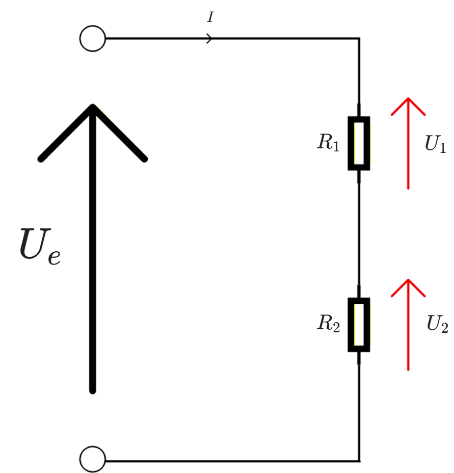
- The same current \(I\) flows through \(R_1\) and \(R_2\).
-
The total voltage is: \(U_e = U_1 + U_2\)
Using Ohm's law:
- \(U_1 = R_1 \times I\)
- \(U_2 = R_2 \times I\)
Since \(I\) is the same in both resistors, the voltages are "divided" according to the resistances.
2. Voltage Divider Formula
The output voltage \(U_s\) is often defined as the voltage across \(R_2\). As shown in the diagram below:
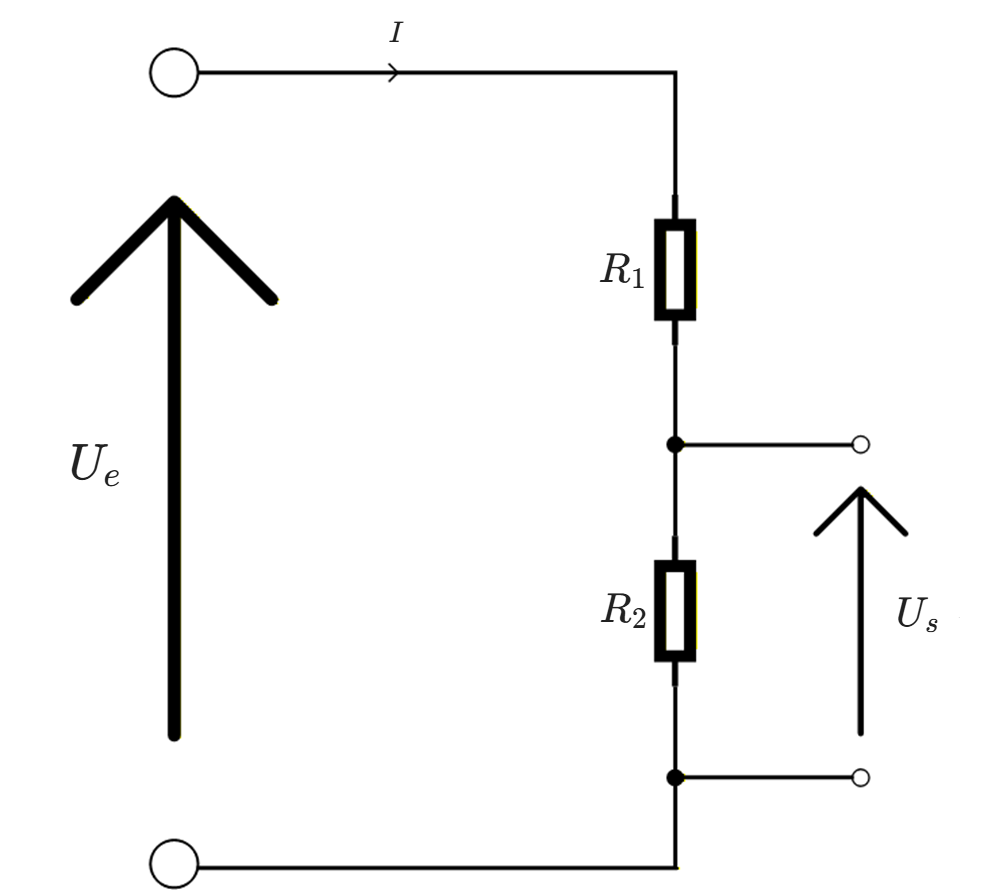
The formula is derived by adding the voltages \(U_1\) and \(U_2\) (which give \(U_e\)), then substituting \(U_1\) and \(U_2\) with \(R_1 \times I\) and \(R_2 \times I\) using Ohm’s law.
A few algebraic steps then allow us to express \(U_s\) in terms of \(U_e\), \(R_1\), and \(R_2\).
Therefore:
- if \(R_2\) is small compared to \(R_1\), the output voltage is small;
- if \(R_2\) is large compared to \(R_1\), the output voltage approaches the input voltage.
We can also choose to measure the voltage across \(R_1\). In this case:
The principle remains the same: the voltage is distributed proportionally across the resistors.
Important: this formula is accurate when the output is measured "no-load" , that is, with a device that draws almost no current (e.g., multimeter in voltmeter mode, high-impedance measurement input).
3. Numerical Example
A voltage divider is supplied with \(U_e = 12\ \mathrm{V}\):
- \(R_1 = 8\ \mathrm{k\Omega}\)
- \(R_2 = 4\ \mathrm{k\Omega}\)
- We measure the voltage across \(R_2\).
Then:
The divider has "reduced" the voltage from \(12\ \mathrm{V}\) to \(4\ \mathrm{V}\).
4. Voltage divider formula (case with a load)
If we connect a load \(R_L\) to the output (a device that consumes current), this load is connected in parallel with \(R_2\); see the new diagram:
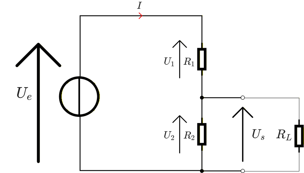
The "lower" resistance is then no longer \(R_2\), but an equivalent resistance:
The output voltage becomes:
We substitute \(R_{\mathsf{eq}}\) and expand:
Key Point: Voltage Divider with Two Resistors
- Two resistors \(R_1\) and \(R_2\) in series supplied by a voltage \(U_e\)
- The output voltage \(U_s\) measured across \(R_2\) is:
- \(U_s = U_e \times \frac{R_2}{R_1 + R_2}\)
- The voltage is distributed proportionally across the resistors.
- This circuit allows you to obtain a lower voltage from a higher voltage.
- The formula is valid if the output is connected to a very high-impedance input ("light" load).
Equivalent Resistance Calculator
Explore the voltage divider: compare the behavior without load (ideal case) and with load (real-world case).
⚡ Source and divider
📊 Results
📉 Comparison (effect of load)
\(k\) compares the load to \(R_2\)